
Optical transmission · 1550 nm
EDFA & 1550 nm Transmitter
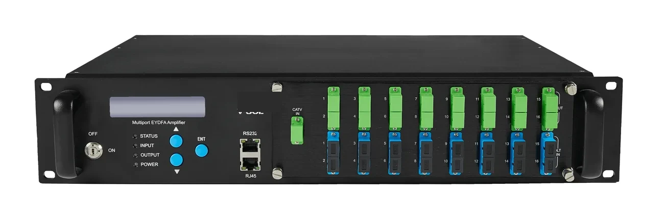
1550 nm optical transmitters and erbium-doped fibre amplifiers for CATV overlay and long-distance transport: direct-modulated 10 dBm and external-modulated 7/9 dBm transmitters, plus 4/8/16/32-port EDFA units at 19/22 dBm.
Updated October 24, 2026
- Wavelength
- 1550 nm
- EDFA ports
- 4 / 8 / 16 / 32
- Output power
- 19 / 22 dBm
- Transmitter
- 7 / 9 / 10 dBm
The short answer
What this product is specified for.
Included in the quotation
- Port count, connector polish and power configuration
- Model-level datasheet and test data
- Optical budget and splitter plan for the ODN
- Export packing, HS code and Incoterm
1550 nm transport is how a CATV signal or a long-haul data link shares the same fibre plant as a PON. The 1550 nm window has lower fibre loss than 1310 nm and supports erbium-doped fibre amplification, so one transmitter can feed a passive split and an EDFA chain without regenerating the RF signal. On a hotel or campus, the CATV headend sits beside the OLT; a WDM coupler combines 1550 nm CATV with 1490/1310 nm PON, and an ONU with a CATV port separates it at the room.
The transmitter choice is direct-modulated or externally modulated. A direct-modulated 10 dBm unit is the economical choice for a small headend and a short span; an externally modulated 7/9 dBm unit avoids the chirp and SBS limits of direct modulation and is preferred when the signal must travel farther or pass a high-power EDFA. The EDFA family covers 4, 8, 16 and 32 output ports at 19 or 22 dBm, so the split can be sized to the number of buildings or floors.
At the subscriber end, a CATV optical receiver takes +2 to −18 dBm at 1550 nm and delivers 47–1000 MHz at 75 Ω with AGC, maintaining ≥81 ± 2 dBµV in the AGC window. Plan the RF level and the optical input together: too high an optical input saturates the receiver, too low degrades MER. The link budget, not the amplifier’s headline power, decides how many splits are possible.
Configuration table
The numbers that decide the fit.
Values are from the model datasheet. Where a value is model-dependent, the table says so instead of guessing.
| Unit | Ports / output | Wavelength | Typical use |
|---|---|---|---|
| Direct-modulated transmitter | 10 dBm | 1550 nm | Small CATV headend, short span |
| External-modulated transmitter | 7 / 9 dBm | 1550 nm | Longer span, high SBS tolerance |
| EDFA | 4 / 8 / 16 / 32 ports | 1550 nm | CATV distribution, long haul |
| CATV optical receiver | 1× OPT + 1× PON + 1× CATV | 1550 ± 10 nm | Subscriber or floor receiver |
EDFA output power and port count are model-specific. Confirm the optical input range, gain and connector type on the datasheet.
Engineering features
What changes on site.
1550 nm low loss
About 0.2 dB/km at 1550 nm vs 0.35 dB/km at 1310 nm, so a long campus or district span needs fewer active points.
4–32 output ports
One EDFA can feed multiple buildings or floors through a passive split, with 19 or 22 dBm output options.
CATV-grade RF
The receiver covers 47–1000 MHz at 75 Ω with AGC and ≥32 dB MER at −14 dBm input, so analogue and digital channels stay within spec.
SBS-aware design
External modulation is the safer choice when the launch power or span approaches the stimulated Brillouin scattering threshold.
WDM with PON
A 1550 nm CATV overlay can share the ODN with 1310/1490 nm PON using a WDM coupler, provided the splitter and connectors are rated for all three windows.
Headend or cabinet
Rack-mount units for a headend; hardened enclosures are quoted for outdoor cabinets. Confirm the operating temperature for the enclosure.
Selection guide
Which configuration fits which site.
Start from the site, not from the model. The table is a starting point; the final check is the optical and power budget.
| Scenario | Transmitter | Amplifier | Note |
|---|---|---|---|
| Small hotel CATV overlay | Direct 10 dBm | 4-port 19 dBm | Short span, 1:8/1:16 split |
| Campus multi-building | External 7/9 dBm | 8/16-port 19 dBm | Check SBS and split loss |
| District / long haul | External 9 dBm | 16/32-port 22 dBm | Plan gain and input power |
| FTTH + CATV | Direct or external | 4/8-port 19 dBm | WDM coupler at the headend |
Do not exceed the receiver input range; a 0 dBm input can saturate a receiver rated to +2 dBm, and a −20 dBm input is below a −18 dBm rating.
Applications
Where this product is used.
Related equipment
Complete the chain.
The product is quoted as part of a chain. These are the parts that usually travel with it.
PON access · OLT
GPON OLT
From a 1-PON gateway to a 112-PON headend.
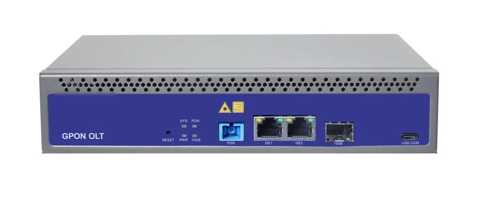
GPON OLT platforms for FTTH, campus and hotel access: 2.5 Gbps downstream and 1.25 Gbps upstream, 1:64 split per PON port and 20 km reach on Class B+ optics. Configurations run from a compact 1-PON gateway with built-in AC to a chassis with up to 112 PON ports.
- Line rate
- 2.5 Gbps ↓ / 1.25 Gbps ↑
- Max split
- 1:64 per PON port
- Reach
- 20 km, Class B+
- PON ports
- 1 – 112
Best for FTTH Access Network · Campus Fibre Network · Outdoor Wireless Coverage
View specifications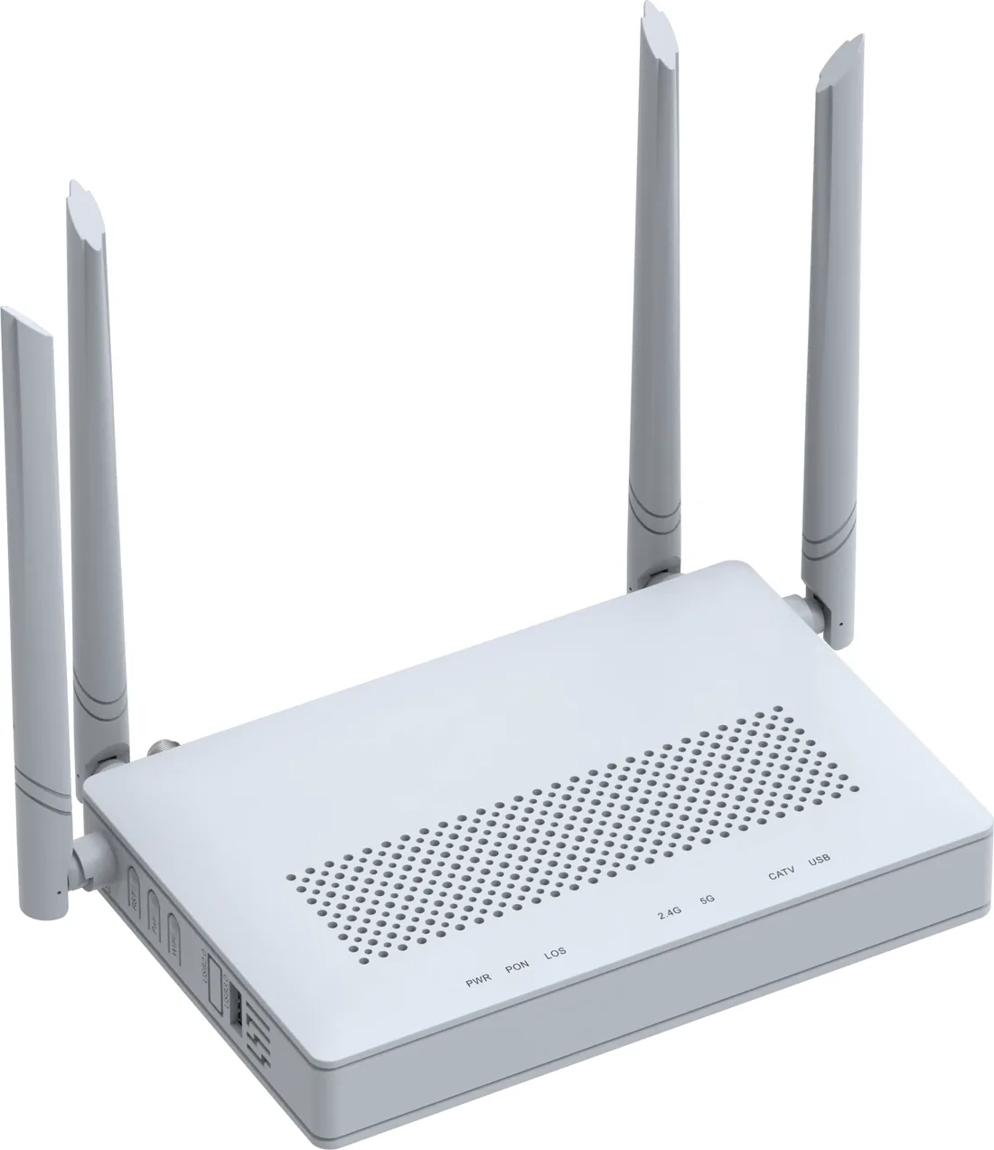
PON access · ONU / ONT
GPON / XPON ONU & ONT
From a 1-GE bridge to a 4-GE Wi-Fi 6 gateway.
XPON ONU and ONT options for FTTH, hotel rooms, offices and outdoor cabinets: 1, 2 or 4 GE ports, Wi-Fi 4/5/6, CATV and POTS options, and 10G PON models. All units are SC single-mode, 20 km, EPON/GPON dual-mode where the model supports it.
- PON
- XPON, EPON/GPON
- User ports
- 1 – 4 × GE
- Wi-Fi
- Wi-Fi 4 / 5 / 6
- Reach
- 20 km
Best for FTTH Access Network · Campus Fibre Network · Outdoor Wireless Coverage
View specifications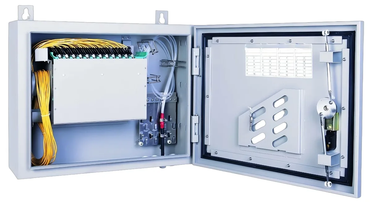
PON access · ODN
Fiber Optic Splitter (PLC)
1×2 to 1×64, SC/UPC or SC/APC.
Planar lightwave circuit splitters from 1×2 to 1×64 for PON ODN construction. Typical insertion loss runs from 3.6 dB at 1×2 to 20.5 dB at 1×64; each batch ships with test data and the connector polish you specify.
- Ratios
- 1×2 – 1×64
- Wavelength
- 1260 – 1650 nm
- Insertion loss
- 3.6 – 20.5 dB
- Connector
- SC/UPC / SC/APC
Best for FTTH Access Network · Campus Fibre Network · CCTV & Surveillance Power
View specifications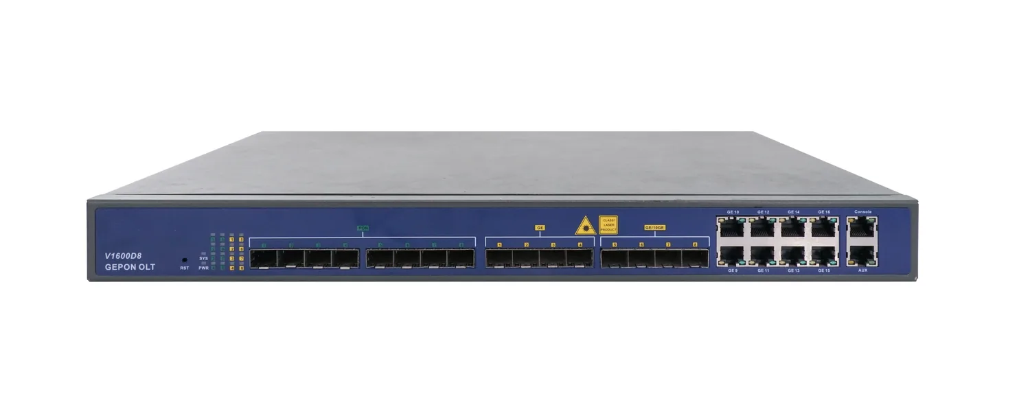
PON access · OLT
8-Port EPON OLT
1U, eight EPON ports, up to 512 ONUs.
A 1U EPON OLT with eight PON ports, 16 uplink ports and a 128 Gbps backplane. It supports 1:64 splitting, 20 km reach and up to 512 ONUs, making it a compact headend for CCTV, campus and small FTTH networks.
- PON ports
- 8 × EPON
- Line rate
- 1.25 Gbps symmetric
- Max ONUs
- 512 (64 per port)
- Backplane
- 128 Gbps
Best for CCTV & Surveillance Power · Campus Fibre Network · FTTH Access Network
View specificationsProduct FAQ
EDFA & 1550 nm Transmitter: questions before the order.
If your question is not here, send the site details and we will answer with the calculation, not a brochure.
Ask an engineerWhat is the difference between direct and external modulation?
Direct modulation modulates the laser current; it is simple and economical but has chirp and SBS limits. External modulation uses a separate modulator, giving lower chirp and better performance over long spans or high launch power.
How many splits can an EDFA feed?
It depends on the output power, the split ratio and the receiver input range. A 19 dBm amplifier with a 1:8 split gives about 10 dBm per output before connector loss; check the receiver’s +2 to −18 dBm window and leave margin.
Can I put CATV on the same fibre as GPON?
Yes, with a WDM coupler at the headend and an ONU with a 1550 nm CATV receiver. The ODN splitters and connectors must work across 1310/1490/1550 nm, which standard PLC modules do.
What is SBS and why does it matter?
Stimulated Brillouin scattering limits how much optical power can be launched into a fibre before the signal is scattered. External modulation and lower launch power help; the exact threshold depends on fibre type and span.
Does the EDFA include the pump laser?
Yes, the EDFA is a complete unit with pump, control and status display. The model datasheet lists the input range, output power and connector type.
Do you supply the WDM coupler and receiver?
Yes. The WDM coupler, CATV receiver, EDFA and transmitter are quoted together so the wavelengths, connector polish and RF level match the headend design.
Next step
Need a EDFA & 1550 nm Transmitter configuration checked?
Send the endpoint count, the longest run, the power condition and the destination. We reply with the configuration, the optical/power budget and the quotation assumptions.
No obligation. The plan states its assumptions so your engineer can check it.