
ODN & accessories · enclosures
ODF & Fiber Enclosures
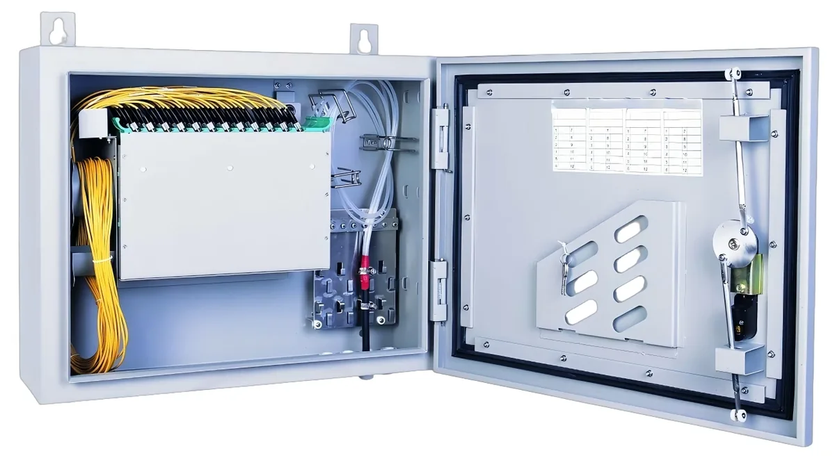
Passive enclosures for the ODN: 1U rack ODFs, wall-mount distribution boxes, splice closures and terminal boxes, with SC/UPC or SC/APC adapters and 4–96 port options. The enclosure format follows the installation point.
Updated October 24, 2026
- Formats
- 1U / wall / closure
- Ports
- 4 – 96
- Adapter
- SC/UPC / SC/APC
- Mount
- Rack / wall / pole
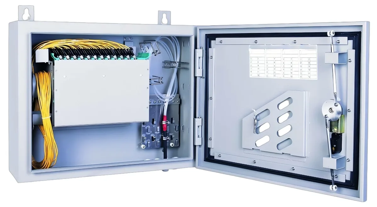
The short answer
What this product is specified for.
Included in the quotation
- Port count, connector polish and power configuration
- Model-level datasheet and test data
- Optical budget and splitter plan for the ODN
- Export packing, HS code and Incoterm
An ODF is where the outside plant meets the equipment. It terminates the incoming cable, stores the splices, holds the adapters and gives the technician a clean patch point. A wall box does the same job in a building riser; a splice closure does it in a vault or on a pole. The format follows the installation point, not the catalogue.
For a headend, a 1U 19-inch ODF with 12, 24 or 48 SC adapters is the usual choice. For a building, a wall-mount box with 8–24 ports and a splice tray is enough. For an outdoor ODN, a splice closure with 24–96 splices and an IP-rated body protects the joints. The adapter polish (SC/UPC or SC/APC) must match the patch cords and the splitter.
The enclosure is part of the optical budget and the maintenance plan. Every adapter pair adds loss; every splice adds about 0.1 dB; a dirty connector can add 1–3 dB. Keep the enclosure accessible for testing and cleaning, label the ports, and leave spare capacity for the next building or floor. The ODF is not a place to hide excess cable.
Configuration table
The numbers that decide the fit.
Values are from the model datasheet. Where a value is model-dependent, the table says so instead of guessing.
| Type | Ports / splices | Mount | Typical use |
|---|---|---|---|
| 1U rack ODF | 12 / 24 / 48 SC | 19-inch rack | Headend / telecom room |
| Wall distribution box | 8 / 16 / 24 SC | Wall | Building riser |
| Splice closure | 24 / 48 / 96 splices | Pole / vault | Outdoor ODN |
| Terminal box | 4 / 8 SC | Wall | Subscriber drop |
| Adapter panel | SC/UPC / SC/APC | Rack / box | Patch point |
Port count, adapter type, splice tray and IP rating are model-specific. Confirm the format and polish on the quotation.
Engineering features
What changes on site.
Rack, wall or pole
The format follows the installation point: 1U ODF in the headend, wall box in the riser, closure in the vault.
Splice protection
A splice tray and a bend-radius guide protect the joints; the closure body provides the IP rating outdoors.
Adapter polish
SC/UPC or SC/APC to match the splitter and patch cords; a mismatch adds loss and reflection.
Cable management
Entry glands, strength-member clamps and a slack tray keep the cable and fibre under control.
Label plan
Label the ports and the cable direction; the as-built label is part of the handover.
Access for testing
Keep the enclosure accessible for a power meter, a cleaning tool and a spare port.
Selection guide
Which configuration fits which site.
Start from the site, not from the model. The table is a starting point; the final check is the optical and power budget.
| Point | Recommended | Why |
|---|---|---|
| Headend | 1U ODF, 24/48 SC | Terminate the feeder and patch to the OLT |
| Building riser | Wall box, 8/16 SC | Distribution and splice point |
| Outdoor ODN | Splice closure, 24/48 | Protect joints in a vault or pole |
| Subscriber | Terminal box, 4/8 SC | Drop cable termination |
Leave 20–30% spare ports for the next phase; a full ODF forces a new enclosure.
Related equipment
Complete the chain.
The product is quoted as part of a chain. These are the parts that usually travel with it.
PON access · ODN
Fiber Optic Splitter (PLC)
1×2 to 1×64, SC/UPC or SC/APC.
Planar lightwave circuit splitters from 1×2 to 1×64 for PON ODN construction. Typical insertion loss runs from 3.6 dB at 1×2 to 20.5 dB at 1×64; each batch ships with test data and the connector polish you specify.
- Ratios
- 1×2 – 1×64
- Wavelength
- 1260 – 1650 nm
- Insertion loss
- 3.6 – 20.5 dB
- Connector
- SC/UPC / SC/APC
Best for FTTH Access Network · Campus Fibre Network · CCTV & Surveillance Power
View specifications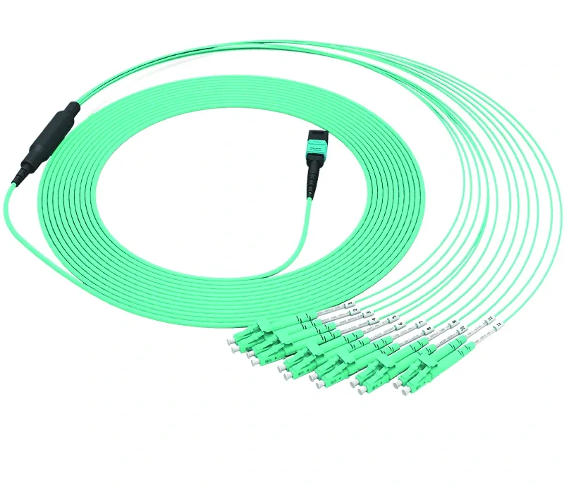
ODN & accessories · fiber cords
Patch Cords, Pigtails & Adapters
SC/LC, UPC/APC, simplex and duplex.
Fiber patch cords, pigtails and adapters for OLT/ODF/ONU links: SC/LC, UPC/APC, simplex/duplex, G.657A2/G.652D, 1–3 m standard lengths, with insertion loss and return loss test data. MPO breakout and copper patch cords are available.
- Connector
- SC / LC
- Polish
- UPC / APC
- Fiber
- G.657A2 / G.652D
- Length
- 1 / 2 / 3 m
Best for FTTH Access Network · Campus Fibre Network · CCTV & Surveillance Power
View specifications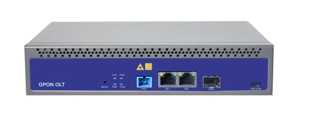
PON access · OLT
GPON OLT
From a 1-PON gateway to a 112-PON headend.
GPON OLT platforms for FTTH, campus and hotel access: 2.5 Gbps downstream and 1.25 Gbps upstream, 1:64 split per PON port and 20 km reach on Class B+ optics. Configurations run from a compact 1-PON gateway with built-in AC to a chassis with up to 112 PON ports.
- Line rate
- 2.5 Gbps ↓ / 1.25 Gbps ↑
- Max split
- 1:64 per PON port
- Reach
- 20 km, Class B+
- PON ports
- 1 – 112
Best for FTTH Access Network · Campus Fibre Network · Outdoor Wireless Coverage
View specifications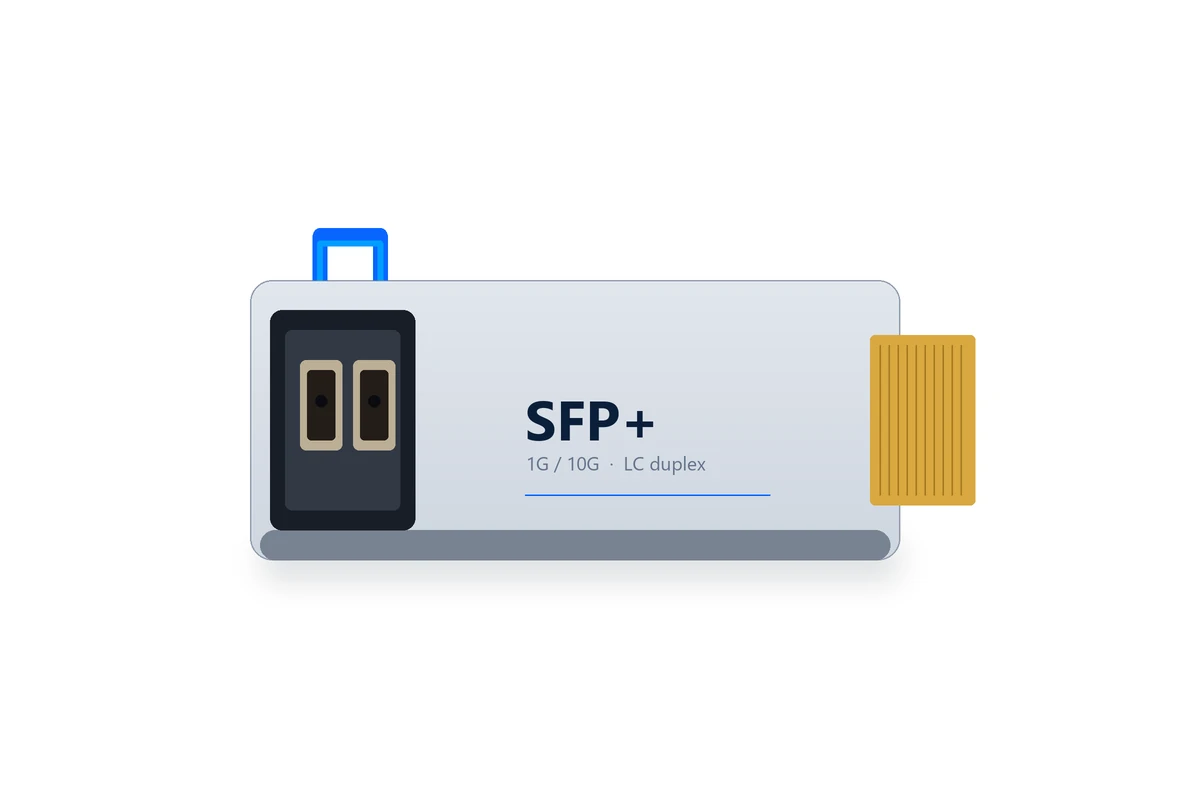
ODN & accessories · optics
SFP & SFP+ Transceivers
1G/10G optics for PON, switches and uplinks.
SFP and SFP+ optical transceivers for PON ports, switch uplinks and 1550 nm links: 1G/10G, 1310/1490/1550 nm, 20/40/80 km, SC/LC, EPON PX20++/+++ and GPON Class B+/C+ options. The exact optic is confirmed with the OLT or switch model.
- Rate
- 1G / 10G
- Reach
- 20 / 40 / 80 km
- Wavelength
- 1310 / 1490 / 1550 nm
- Connector
- SC / LC
Best for FTTH Access Network · Campus Fibre Network · Industrial & Tunnel Network
View specificationsProduct FAQ
ODF & Fiber Enclosures: questions before the order.
If your question is not here, send the site details and we will answer with the calculation, not a brochure.
Ask an engineerWhat is the difference between an ODF and a splitter box?
An ODF terminates and patches fibres; a splitter box contains a PLC splitter and distributes the outputs. Some boxes combine both, but they are different functions.
UPC or APC?
SC/UPC for data PON; SC/APC for CATV and long spans. The ODF adapter, patch cord and splitter must use the same polish or a hybrid cord.
How many spare ports?
Leave 20–30% spare for the next phase. A 24-port ODF with 18 used ports is a reasonable planning target.
Can the box be used outdoors?
Only an IP-rated outdoor closure or box. A wall box for an indoor riser is not a substitute for a pole or vault closure.
Does the ODF include the splitters?
Not always. The ODF can be supplied empty or loaded with PLC splitters; confirm the configuration on the quotation.
How do I clean the adapters?
Use a one-click cleaner and inspect with a scope. A dirty SC connector can add 1–3 dB and cause intermittent ONU drops.
Next step
Need a ODF & Fiber Enclosures configuration checked?
Send the endpoint count, the longest run, the power condition and the destination. We reply with the configuration, the optical/power budget and the quotation assumptions.
No obligation. The plan states its assumptions so your engineer can check it.