
Application · perimeter
Perimeter Security Power
Perimeter cameras, fence sensors and warning devices are spread over hundreds of metres with few power points. A fibre backbone with PoF drops at the no-mains points keeps the copper exposure short and the run within 200 m.
Updated October 24, 2026
- Copper limit
- 100 m
- PoF limit
- 200 m
- PoF power
- 12 W / port
- PON reach
- 20 km
The engineering problem
Why the obvious answer fails.
The endpoint is small; the distance, the power and the environment are not. Three paragraphs explain where the design usually breaks.
A perimeter is a line, not a room. Cameras, fence sensors, sirens and illuminators are spaced along a fence that may be 500 m to several kilometres long. The nearest powered building is often at one end. Copper Ethernet cannot follow the fence beyond 100 m per run, and each copper segment is a lightning path.
The loads are small but intermittent. A fence camera is 8–12 W; a siren or illuminator can draw 20–50 W for short periods; a heater in a cold climate adds more. A design that sizes for the average load will trip on the first cold night or alarm event.
The robust pattern is a fibre ring or spur along the perimeter, with small cabinets at 200–300 m intervals. Each cabinet holds a PoE switch or a PoF splitter; only the final 200 m to a device is copper. That limits both the surge exposure and the voltage drop.
Path comparison
Four paths, one decision.
The correct path is the one that matches the endpoint power, the distance and the presence of mains. Do not compare only on cable price.
| Path | Reach | Power at the endpoint | Mains at endpoint | Best for | Limits |
|---|---|---|---|---|---|
| Copper PoE | 100 m channel | 15.4 / 30 W at the source (af / at) | Required for the switch | Devices within 100 m of a powered cabinet | Cable loss, surge path, no reach beyond 100 m |
| PoE extender | 200 – 500 m with hops | Reduced at each hop | Required at every extender | Retrofit where a mid-point has power | Another powered box outdoors; still copper |
| Power over Fiber | Up to 200 m per port | Up to 12 W per port | Not required | Ceiling APs, pole cameras, readers, sensors | 12 W per port, hybrid cable, 200 m limit |
| Fibre + local PoE switch | 20 km PON backhaul | Local switch budget | Required at the local cabinet | Cabinets, buildings, dense clusters | Needs a powered cabinet and a switch |
The correct path is the one that matches the endpoint power, the distance and the presence of mains. Do not compare only on cable price.
Design approach
How we lay it out.
Draw the fence as a line
Mark every device, the nearest power point and the distance between them. Group devices into 200–300 m zones; each zone gets a cabinet or a PoF splitter feed.
Keep the backbone optical
Run fibre along the fence, not copper. A fibre ring with RSTP gives a second path if a cable is cut at one point. Use armoured or ducted cable for burial.
Size for peak, not average
Add the camera, heater, illuminator and siren peaks. If a zone exceeds the PoE or PoF budget, split the zone or move the cabinet closer.
Bill of materials
A starting BOM.
Quantities follow the endpoint count and the number of cabinets. Adjust after the site survey.
| Item | Specification | Quantity basis |
|---|---|---|
| OLT | 8-port EPON/GPON | 1 per perimeter headend |
| Industrial PoE switch | Wide temperature, redundant DC, ring | 1 per 200–300 m zone |
| PoF splitter | 8 outputs, 12 W per port | 1 per 8 low-power devices |
| Hybrid PoF cable | 20/50 m, UV-rated conduit outdoors | 1 per device + spare |
| Fence camera | 8–12 W fixed; check heater | Per design |
| SPD | At cabinet and device entry | Per local code |
For a 1 km perimeter, four to six zones are typical. Confirm the fibre route, power points and burial depth.
Numbers to check
The design rules.
| Design rule | Value to confirm |
|---|---|
| Zone length | 200 – 300 m |
| PoF reach | 200 m per port |
| PoF load | 12 W per port |
| Camera load | 8 – 12 W; heater extra |
| Ring recovery | RSTP/MSTP or dedicated ring |
| Surge | SPD at every cabinet and device entry |
Recommended equipment
What this design usually uses.
PoE switching · hardened
Industrial PoE Switch
Hardened switching for tunnels, roads and plants.
Industrial PoE switching specified per project: DIN-rail mounting, wide-temperature operation, redundant DC input, higher surge immunity and ring recovery for tunnels, highways, plants and perimeter sites.
- Mounting
- DIN rail / wall
- Temperature
- Wide-range model
- Power
- Redundant DC
- Network
- Ring / RSTP
Best for Industrial & Tunnel Network · Perimeter Security Power · Parking Lot Camera System
View specifications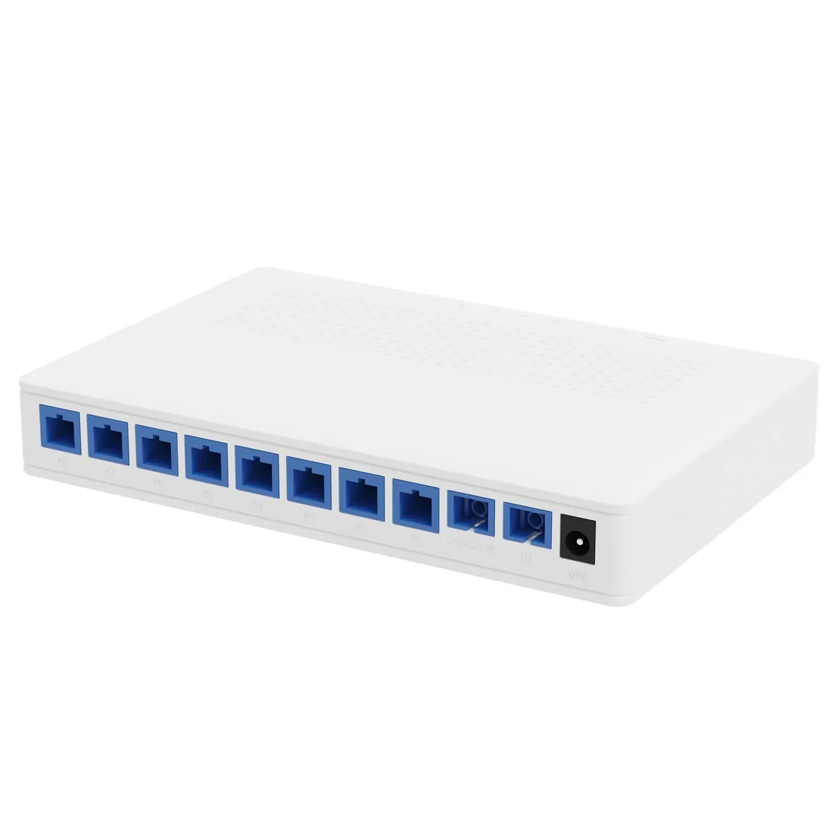
Power over Fiber · access
PoF Switch & PoF ONU
One hybrid cable to the ceiling: data and 12 W.
A Power-over-Fiber access set: an optical gateway, an 8-output PoF power splitter, hybrid PoF cable and a ceiling Wi-Fi 6 ONU. Each output delivers up to 12 W to 200 m, so ceiling APs and cameras run without a local mains socket.
- Power per port
- Up to 12 W
- Reach
- Up to 200 m
- Outputs
- 8 + 1 cascade
- Wi-Fi
- Wi-Fi 6 AX3000
Best for Outdoor Wireless Coverage · Campus Fibre Network · Parking Lot Camera System
View specifications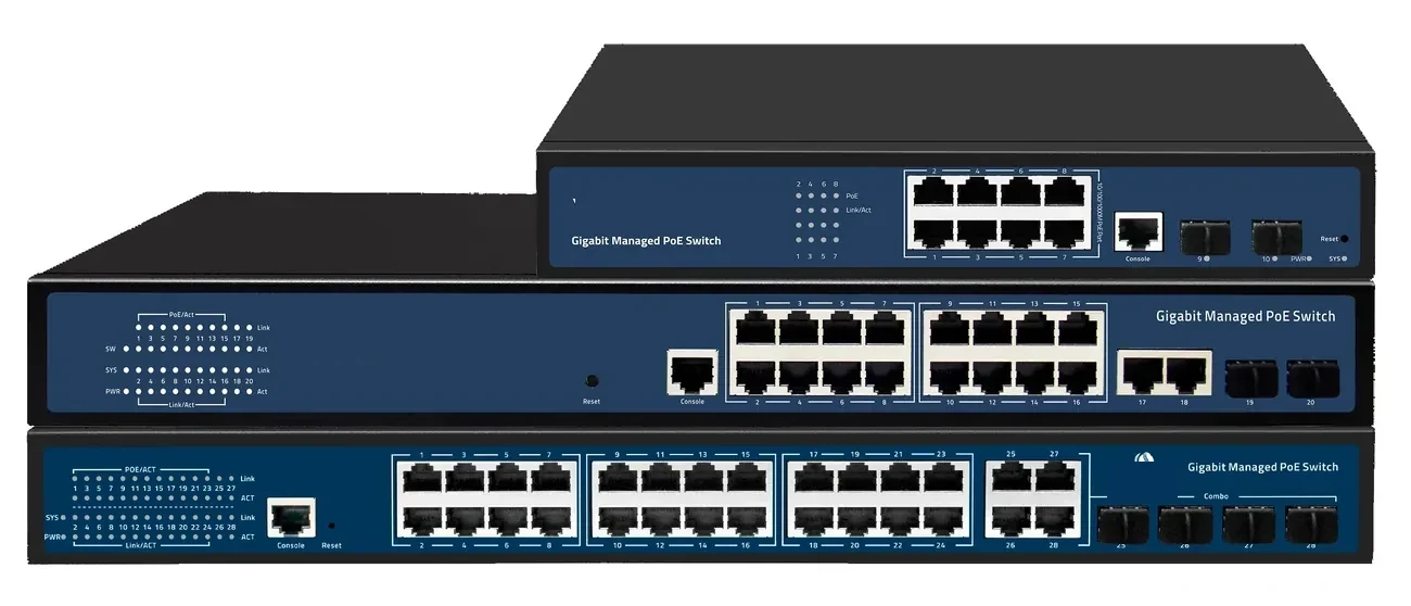
PoE switching · managed & unmanaged
PoE Switches
8 to 48 PoE ports, with 10G and 100G uplinks.
PoE switch families from compact 4–8 port units to 48-port Layer 3 switches with 100G uplinks. IEEE 802.3af/at power, VLAN and IGMP isolation, and a 100 m copper limit that decides where the fibre has to take over.
- Ports
- 4 – 48 × GE PoE
- Uplinks
- GE / 10G / 100G
- Power
- 802.3af / at
- Distance
- 100 m copper
Best for CCTV & Surveillance Power · Parking Lot Camera System · Perimeter Security Power
View specifications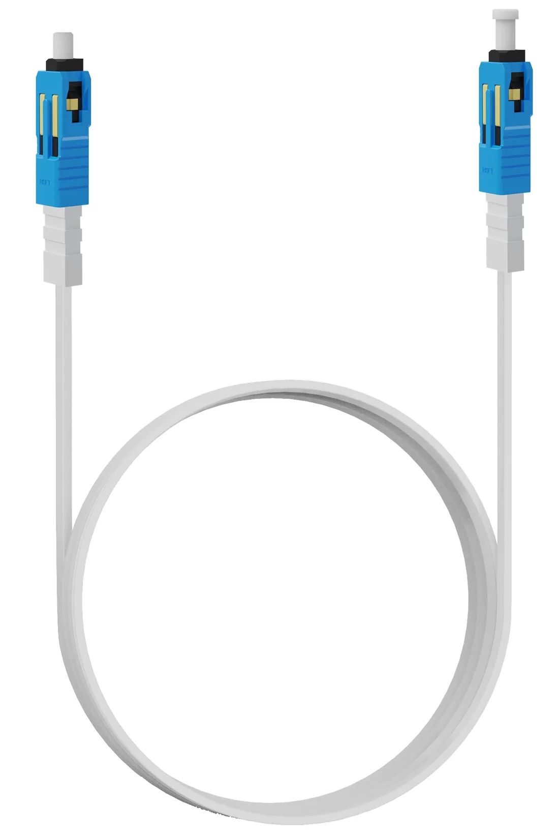
Power over Fiber · cable
Hybrid PoF Cable
G.657A2 fibre and copper in one flat jacket.
A flat hybrid cable with one G.657A2 fibre and a copper pair, terminated SC/UPC and supplied in 3, 20 or 50 m lengths. Attenuation is ≤0.4 dB/km at 1310 nm and ≤0.3 dB/km at 1550 nm; the jacket is rated −20 to +80 °C.
- Fibre
- G.657A2, single core
- Attenuation
- ≤0.4 / ≤0.3 dB/km
- Lengths
- 3 / 20 / 50 m
- Temperature
- −20 to +80 °C
Best for Outdoor Wireless Coverage · Parking Lot Camera System · Bollard & Access Control Power
View specificationsApplication FAQ
Perimeter Security Power: site questions.
If your question is not here, send the site details and we will answer with the calculation, not a brochure.
Ask an engineerCan I run PoE along a fence for 500 m?
No. Each copper run is limited to 100 m. Use a fibre backbone with cabinets every 200–300 m, or PoF drops to individual devices within 200 m of a splitter.
How do I protect perimeter cameras from lightning?
Keep the backbone optical, keep copper drops short, use shielded enclosures bonded to earth, and install surge protective devices at the cabinet and device entry. Follow local code and the site’s lightning risk assessment.
What load should I plan per fence camera?
8–12 W for a fixed camera, plus heater and illuminator if present. A camera with a 15 W heater and a 10 W camera is a 25 W load; check the PoE class and budget.
Can PoF power a fence sensor?
Yes if the sensor and its interface draw under 12 W. Many fence sensors are low-power; confirm the peak and the connector type.
Do I need a ring or a spur?
A ring is preferred for long perimeters because a single cable cut does not isolate the far end. A spur is acceptable for a short perimeter with a single entry point.
How many devices per PoF splitter?
Eight, one per output. If the perimeter has more than eight low-power devices in a zone, use a second splitter or a local PoE switch.
Next step
Planning Perimeter Security Power?
Send the device list, the longest run, the mains condition and the country. We return the path, the BOM and the budget assumptions.
No obligation. The plan states its assumptions so your engineer can check it.