
Power over Fiber · splitter
PoF Power Splitter
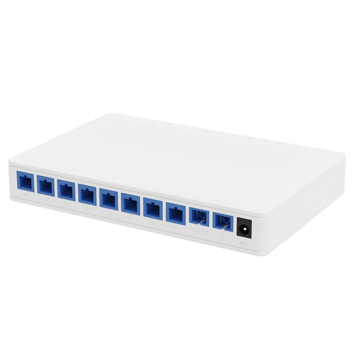
A 1×9 PoF power splitter that combines an optical splitter and a 48 V DC power distributor in one box. It feeds eight PoF ONUs at up to 12 W each to 200 m and provides a cascade port for a second splitter.
Updated October 24, 2026
- Split
- 1×9 (8 + cascade)
- Output power
- ≤12 W per port
- Supply
- 48 V DC, 120 W
- Insertion loss
- ≤16.5 dB output
The short answer
What this product is specified for.
Included in the quotation
- Port count, connector polish and power configuration
- Model-level datasheet and test data
- Optical budget and splitter plan for the ODN
- Export packing, HS code and Incoterm
The PoF power splitter is the distribution point of a Power-over-Fiber network. One hybrid cable arrives from the gateway; eight hybrid cables leave to ceiling APs, cameras or readers. Inside the box, a 1×9 PLC splits the optical signal and a 48 V bus splits the DC power. The eighth output plus the cascade port is what makes the unit a distribution node rather than a simple splitter.
The optical ratings are the ones that matter for the link budget: ≤16.5 dB insertion loss on each output, ≤2.3 dB on the cascade port, 1260–1650 nm operating range and a choice of SC/UPC or SC/APC connectors. The power side is rated 48 V DC in and out, 0.25 A nominal and 0.5 A maximum per port, from a 120 W adapter. At 48 V, 0.25 A is 12 W; the 0.5 A ceiling is a short-term limit, not a continuous load rating.
Mount it on a wall or a desktop near the gateway, keep the hybrid cable bends above the minimum radius and label each output with the AP or camera it feeds. Because the unit distributes both light and power, a fault on one output does not take down the others; the optical split still has a common input, so a dirty connector at the input affects every port.
Configuration table
The numbers that decide the fit.
Values are from the model datasheet. Where a value is model-dependent, the table says so instead of guessing.
| Parameter | Value |
|---|---|
| Split ratio | 1×9 (8 output ports + 1 cascade port) |
| Output insertion loss | ≤16.5 dB |
| Cascade insertion loss | ≤2.3 dB |
| Operating wavelength | 1260 – 1650 nm |
| Connector | SC/UPC or SC/APC |
| Input / output voltage | 48 V DC / 48 V DC |
| Power supply | 120 W adapter |
| Output current | 0.25 A rated; 0.5 A maximum per port |
| Outputs | 8 |
| PoE protocol | PoE+ / PoE, IEEE 802.3at/af |
| Dimensions | 180 × 120 × 26 mm |
| Installation | Desktop or wall mounted |
Power per port is a rating, not a guarantee at every cable length. Calculate voltage drop for the actual hybrid cable and load.
Engineering features
What changes on site.
Optical and power in one node
One enclosure splits the light and the 48 V bus, so the installer terminates one input and eight outputs instead of building a separate power distribution board.
Cascade without a second headend
The cascade port drives a second splitter for 16 APs. It adds ≤2.3 dB, far less than a second home-run fibre.
Per-port protection
Each output is current-limited. A short on one drop does not remove power from the other seven.
Small enough for a riser
180 × 120 × 26 mm, wall or desktop mount. It fits a telecom box, a riser cupboard or the back of a ceiling access panel.
Standard 48 V ecosystem
48 V DC input matches common PoE supplies and battery plants; the output is compatible with 802.3af/at loads through the PoF ONU.
Labelled outputs
Number each output and record it on the as-built. Fault finding on a PoF floor starts with the port number, not with a tone probe.
Selection guide
Which configuration fits which site.
Start from the site, not from the model. The table is a starting point; the final check is the optical and power budget.
| Load plan | Ports used | Cascade | Total DC load |
|---|---|---|---|
| 8 × 8 W APs | 8 | No | 64 W |
| 8 × 10 W APs | 8 | No | 80 W |
| 8 × 12 W APs | 8 | No | 96 W (at the 120 W supply limit) |
| 16 × 8 W APs | 8 + 8 | Yes | 128 W across two supplies |
The 120 W adapter is the input limit. Eight ports at 12 W already reach 96 W before cable loss; do not plan a 16-port load on one adapter.
Integration
Where it sits in the chain.
The PoF chain starts at the optical gateway, passes through the power splitter and ends at the ceiling ONU. The optical budget and the 48 V DC budget are calculated together.
- One bill of materials for the whole chain
- Connector polish and PON mode confirmed before order
- Model-level test data supplied with the shipment
Applications
Where this product is used.
Related equipment
Complete the chain.
The product is quoted as part of a chain. These are the parts that usually travel with it.
Power over Fiber · access
PoF Switch & PoF ONU
One hybrid cable to the ceiling: data and 12 W.
A Power-over-Fiber access set: an optical gateway, an 8-output PoF power splitter, hybrid PoF cable and a ceiling Wi-Fi 6 ONU. Each output delivers up to 12 W to 200 m, so ceiling APs and cameras run without a local mains socket.
- Power per port
- Up to 12 W
- Reach
- Up to 200 m
- Outputs
- 8 + 1 cascade
- Wi-Fi
- Wi-Fi 6 AX3000
Best for Outdoor Wireless Coverage · Campus Fibre Network · Parking Lot Camera System
View specifications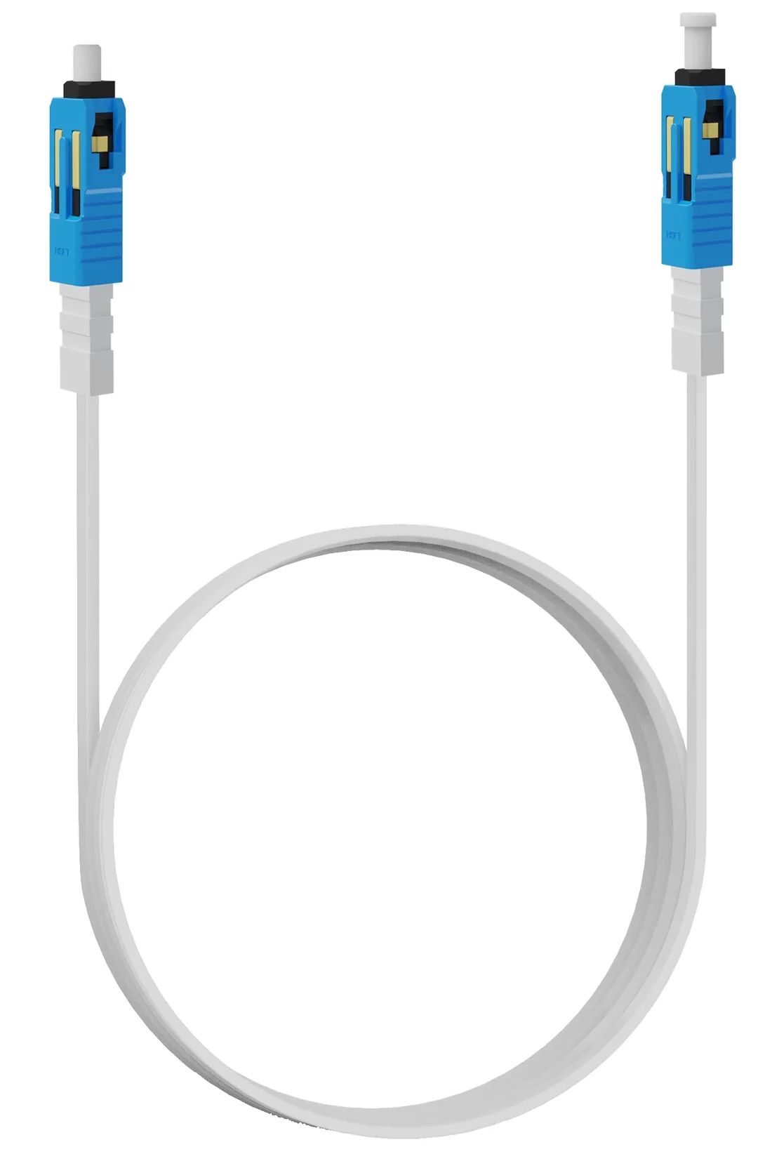
Power over Fiber · cable
Hybrid PoF Cable
G.657A2 fibre and copper in one flat jacket.
A flat hybrid cable with one G.657A2 fibre and a copper pair, terminated SC/UPC and supplied in 3, 20 or 50 m lengths. Attenuation is ≤0.4 dB/km at 1310 nm and ≤0.3 dB/km at 1550 nm; the jacket is rated −20 to +80 °C.
- Fibre
- G.657A2, single core
- Attenuation
- ≤0.4 / ≤0.3 dB/km
- Lengths
- 3 / 20 / 50 m
- Temperature
- −20 to +80 °C
Best for Outdoor Wireless Coverage · Parking Lot Camera System · Bollard & Access Control Power
View specifications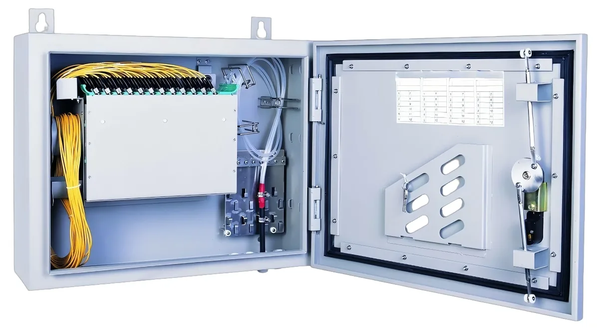
PON access · ODN
Fiber Optic Splitter (PLC)
1×2 to 1×64, SC/UPC or SC/APC.
Planar lightwave circuit splitters from 1×2 to 1×64 for PON ODN construction. Typical insertion loss runs from 3.6 dB at 1×2 to 20.5 dB at 1×64; each batch ships with test data and the connector polish you specify.
- Ratios
- 1×2 – 1×64
- Wavelength
- 1260 – 1650 nm
- Insertion loss
- 3.6 – 20.5 dB
- Connector
- SC/UPC / SC/APC
Best for FTTH Access Network · Campus Fibre Network · CCTV & Surveillance Power
View specifications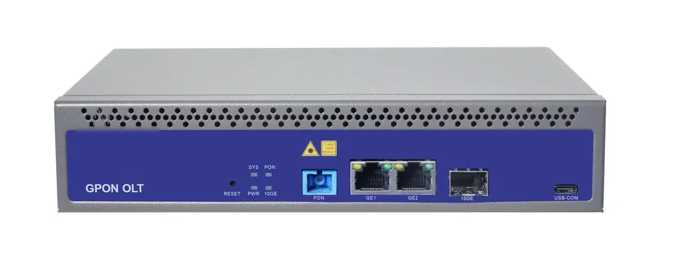
PON access · OLT
GPON OLT
From a 1-PON gateway to a 112-PON headend.
GPON OLT platforms for FTTH, campus and hotel access: 2.5 Gbps downstream and 1.25 Gbps upstream, 1:64 split per PON port and 20 km reach on Class B+ optics. Configurations run from a compact 1-PON gateway with built-in AC to a chassis with up to 112 PON ports.
- Line rate
- 2.5 Gbps ↓ / 1.25 Gbps ↑
- Max split
- 1:64 per PON port
- Reach
- 20 km, Class B+
- PON ports
- 1 – 112
Best for FTTH Access Network · Campus Fibre Network · Outdoor Wireless Coverage
View specificationsProduct FAQ
PoF Power Splitter: questions before the order.
If your question is not here, send the site details and we will answer with the calculation, not a brochure.
Ask an engineerIs this the same as a PLC optical splitter?
It contains a 1×9 PLC, but it also distributes 48 V DC. A standard PLC splitter only splits light and cannot power a PoF ONU.
How much power reaches the ONU at 50 m?
The port is rated 12 W at 48 V. At 50 m the copper loop resistance reduces the voltage; the ONU’s input range and the cable cross-section decide the usable power. Use the cable resistance from the datasheet and leave 20% headroom.
Can I mix PoF and standard PON ONUs on the same splitter?
The optical outputs can feed standard ONUs, but only PoF ONUs accept power over the hybrid cable. A standard ONU needs its own DC adapter.
What connector polish should I order?
Choose SC/UPC or SC/APC to match the gateway and ONU. Do not mix polish types without hybrid patch cords; a mismatch adds loss and reflection.
Does the splitter need a ground?
The enclosure is passive, but the 48 V supply and the building’s bonding system determine the grounding. Follow local electrical code and bond the supply return at one point only.
How do I monitor the outputs?
The splitter has status LEDs for input power and outputs. For remote monitoring, use a managed PoE/PoF supply or a gateway that reports PoF port status.
Next step
Need a PoF Power Splitter configuration checked?
Send the endpoint count, the longest run, the power condition and the destination. We reply with the configuration, the optical/power budget and the quotation assumptions.
No obligation. The plan states its assumptions so your engineer can check it.