
Positioning technology
Power over Fiber, without the mythology.
A hybrid cable carries data on fibre and 48 V DC on a copper pair. It reaches 200 m and delivers up to 12 W per port. That is enough for a ceiling AP, a fixed camera or a reader — and not enough for everything else.
- Reach
- 200 m / port
- Power
- 12 W / port
- Outputs
- 8 + cascade
- Cable
- Fibre + 48 V DC
01 / Definition
What PoF actually is.
It is not “PoE over fibre” and it is not a 20 km power link. It is a hybrid cable system for the last 200 m.
A hybrid cable contains one optical fibre and a copper pair in the same flat jacket. The fibre carries the PON signal; the copper carries 48 V DC. At the ceiling, a PoF ONU separates the two and powers the radio or the camera.
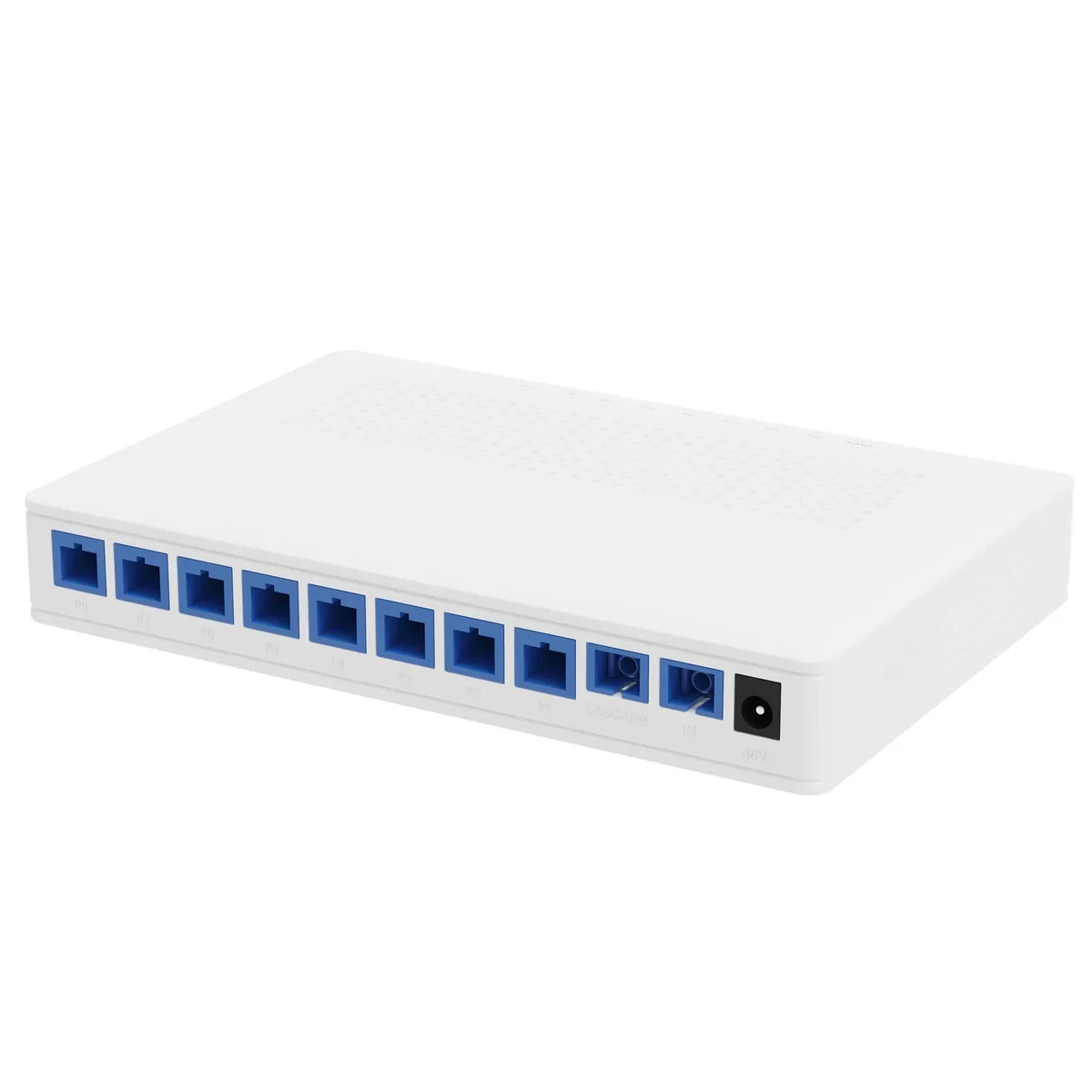
The splitter is the distribution node. It takes one hybrid input and provides eight powered outputs plus one cascade port. The optical side is a 1×9 PLC with ≤16.5 dB insertion loss per output; the power side is a 48 V bus rated at 12 W per port from a 120 W supply.
The system is engineered for the case where a mains socket is absent or expensive: ceiling APs, pole cameras, card readers, intercoms and sensors. It is not a general replacement for a powered cabinet.
Cable
G.657A2 + copper
3 / 20 / 50 m, SC/UPC
Splitter
1×9 PLC + 48 V bus
8 outputs + cascade
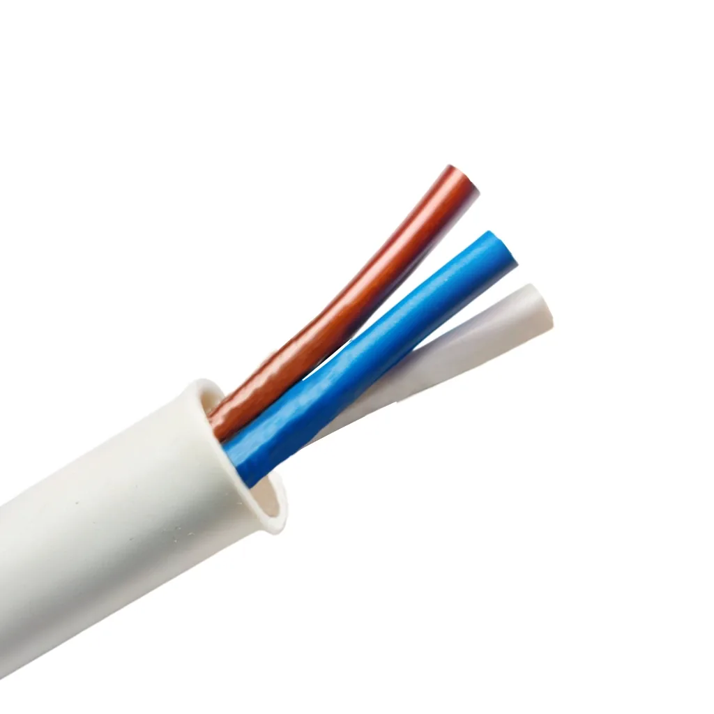
Hybrid cable cross-section: one fibre in a tight sleeve, a copper pair, reinforcement and a PVC jacket. Data on the fibre, 48 V DC on the pair.
02 / Topology
One gateway, one splitter, eight endpoints.
The gateway terminates the PON and sources the DC. The splitter distributes both. The ceiling ONU terminates both at the far end.
Optical gateway
1× GPON + 2× GE + 1× 10GE SFP+, built-in software AC, PoF source.
PoF splitter
1×9 PLC, 8 outputs + 1 cascade, 120 W supply, 48 V DC, ≤12 W per port.
PoF ONU / AP
1× XPON PoF + 1× GE + Wi-Fi 6 AX3000, ceiling mount, zero-touch.
Typical configurations
Three ways to lay out the PoF floor.
The same gateway and splitter can cover a single corridor, two linked floors or a mixed PoF/PoE floor. Quantities are confirmed on the quotation.
8 ceiling APs
1 optical gateway + 1 PoF splitter + 8 hybrid cables + 8 PoF APs
1 gateway, 1 splitter, 8 cables (3/20/50 m), 8 PoF APs
One splitter, eight ports used; plan the 120 W supply and cable drop.
16 ceiling APs
1 optical gateway + 2 splitters (cascade) + 16 hybrid cables + 16 PoF APs
1 gateway, 2 splitters, 16 cables, 16 PoF APs
The second splitter runs from the cascade port; check the optical budget and the supply headroom.
8 APs + PoE MDU
1 optical gateway + 1 optical splitter + 1 PoF splitter + 8 PoF APs + 1–7 PoE MDUs
1 gateway, 1 optical splitter, 1 PoF splitter, 8 cables, 8 PoF APs, PoE MDUs
Keep the PoF and PoE power domains separate; size each MDU from its own device list.
03 / Path comparison
PoF is one of four paths, not the default.
Use the endpoint load, the distance and the mains condition to choose. PoF fills the 100–200 m gap where a mains spur is expensive; it does not replace PoE inside 100 m.
| Path | Reach | Endpoint power | Mains at endpoint | Best for |
|---|---|---|---|---|
| Copper PoE | 100 m channel | 15.4 / 30 W at source | Switch needs mains | Devices within 100 m of a powered cabinet |
| PoE extender | 100 m per hop; 200–500 m typical | Reduced by each hop | Yes, at each extender | Retrofit with a powered mid-point |
| Power over Fiber | Up to 200 m per port | Up to 12 W per port | No | Ceiling APs, pole cameras, readers |
| Fibre + local PoE | PON 20 km; local copper 100 m | Local switch budget | Yes, at the local cabinet | Clusters and higher loads |
Values are industry-standard planning figures. The actual endpoint power depends on cable resistance, length and load; calculate the voltage drop and keep 20% headroom.
Download the path comparison (CSV)04 / Scope
What it powers, and what it does not.
The 12 W limit is the design rule. If the device exceeds it, PoF is the wrong tool.
Within the 12 W envelope
- Wi-Fi 6 ceiling AP, 10–15 W
- Fixed CCTV camera, 6–12 W
- Card reader / intercom, 5–20 W (check peak)
- Fence sensor, environmental sensor, controller
- Small display or signage controller under 12 W
Outside the envelope
- PTZ camera with heater, 25–60 W
- Bollard or gate motor, hundreds of watts
- High-power outdoor AP above 12 W
- Large display or heated enclosure
- Any run beyond 200 m
05 / Specifications
The numbers that go in the quote.
| Parameter | Splitter | Cable | Ceiling ONU / AP |
|---|---|---|---|
| Optical | 1×9 PLC, 1260–1650 nm, ≤16.5 dB out, ≤2.3 dB cascade | G.657A2, ≤0.4 dB/km @1310, ≤0.3 dB/km @1550 | 1× XPON PoF input, 20 km reach |
| Power | 48 V DC in/out, 120 W supply, 0.25 A rated (0.5 A max) per port | Copper pair in the hybrid jacket | Powered over the hybrid cable; DC 12 V adapter optional |
| Connector | SC/UPC or SC/APC | SC/UPC | SC/UPC |
| Reach | 200 m per port | 3 / 20 / 50 m standard | Wi-Fi 6 AX3000, 5 internal antennas |
| Environment | Wall / desktop mount, 180 × 120 × 26 mm | −20 to +80 °C, 4.2 × 1.8 mm | Ceiling mount; confirm the operating range |
Values are from the model datasheets. The actual power at the endpoint depends on cable length, copper resistance and load; calculate the voltage drop and keep 20% headroom.
06 / Honest limits
Four limits to design around.
12 W per port
The splitter output rating. A PTZ heater or a motor is outside it; use a local switch or a mains feed.
200 m per port
Not 500 m and not 20 km. Beyond 200 m, fibre to a local cabinet is the answer.
One splitter, eight loads
The splitter is a single point of failure for its group. Keep a spare or split critical loads across two units.
Copper power pair
The fibre is dielectric; the 48 V pair is not. Protect it at the entry and bond the housing.
07 / Where it fits
The places where 200 m changes the design.
Outdoor Wireless Coverage
Ceiling and pole APs without a local mains drop.
Parking Lot Camera System
Pole cameras and lot APs without trenching power.
Bollard & Access Control Power
Power at the column, without a mains trench.
PoF equipment
All productsPower over Fiber · access
PoF Switch & PoF ONU
One hybrid cable to the ceiling: data and 12 W.
A Power-over-Fiber access set: an optical gateway, an 8-output PoF power splitter, hybrid PoF cable and a ceiling Wi-Fi 6 ONU. Each output delivers up to 12 W to 200 m, so ceiling APs and cameras run without a local mains socket.
- Power per port
- Up to 12 W
- Reach
- Up to 200 m
- Outputs
- 8 + 1 cascade
- Wi-Fi
- Wi-Fi 6 AX3000
Best for Outdoor Wireless Coverage · Campus Fibre Network · Parking Lot Camera System
View specificationsPower over Fiber · splitter
PoF Power Splitter
Eight outputs, 12 W each, one cascade port.
A 1×9 PoF power splitter that combines an optical splitter and a 48 V DC power distributor in one box. It feeds eight PoF ONUs at up to 12 W each to 200 m and provides a cascade port for a second splitter.
- Split
- 1×9 (8 + cascade)
- Output power
- ≤12 W per port
- Supply
- 48 V DC, 120 W
- Insertion loss
- ≤16.5 dB output
Best for Outdoor Wireless Coverage · Parking Lot Camera System · Bollard & Access Control Power
View specifications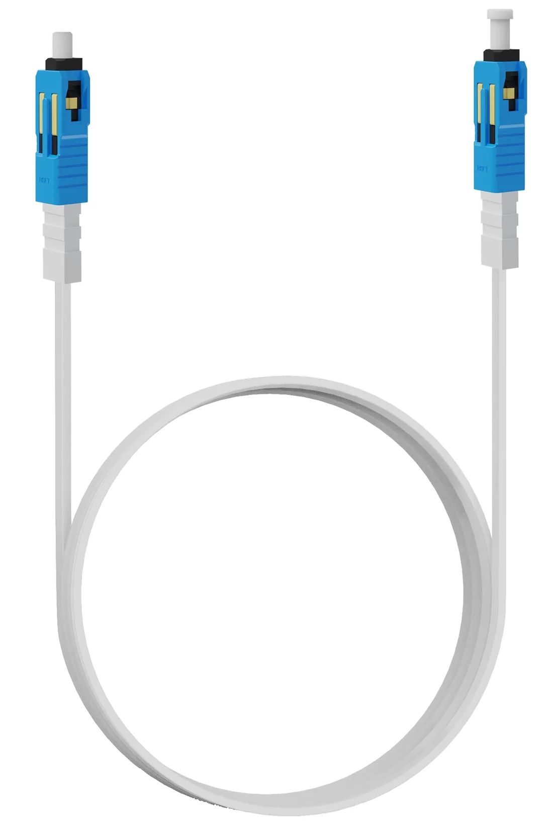
Power over Fiber · cable
Hybrid PoF Cable
G.657A2 fibre and copper in one flat jacket.
A flat hybrid cable with one G.657A2 fibre and a copper pair, terminated SC/UPC and supplied in 3, 20 or 50 m lengths. Attenuation is ≤0.4 dB/km at 1310 nm and ≤0.3 dB/km at 1550 nm; the jacket is rated −20 to +80 °C.
- Fibre
- G.657A2, single core
- Attenuation
- ≤0.4 / ≤0.3 dB/km
- Lengths
- 3 / 20 / 50 m
- Temperature
- −20 to +80 °C
Best for Outdoor Wireless Coverage · Parking Lot Camera System · Bollard & Access Control Power
View specificationsPoF FAQ
PoF questions, answered without the hype.
If your question is not here, send the site details and we will answer with the calculation, not a brochure.
Ask an engineerIs Power over Fiber a standard?
Not in the IEEE 802.3 sense. PoE is standardized power over Ethernet pairs; PoF here is a system design that uses a hybrid cable (fibre plus a copper pair), a PoF power splitter and a PoF ONU. Ask for the cable, splitter and ONU datasheets as a set.
How much power and distance does it provide?
Up to 12 W per output port and up to 200 m per port, with an 8-output splitter and a 120 W 48 V DC supply. The actual power at the device depends on cable length and voltage drop.
What can it power?
Low-power endpoints: Wi-Fi 6 ceiling APs (10–15 W), fixed cameras (6–12 W), card readers and intercoms (5–20 W), sensors and small controllers. It is not a motor or heater supply.
What can it not power?
A PTZ camera with a heater, a bollard hydraulic pump, a large display or a high-power access point above 12 W. Those need a local PoE switch or a mains feed.
Is the fibre surge-proof?
The fibre is dielectric, so the data path is isolated. But the hybrid cable still contains a 48 V copper pair, and the endpoint has a housing and earth. Protect the power pair at the entry and bond the housing; do not treat the cable as a purely dielectric line.
Can it run on a third-party OLT?
The ONU is XPON and can register on a compatible PON OLT, but the zero-touch AC and roaming features are tied to the gateway/OLT ecosystem. Confirm the OLT, firmware and management profile before mixing vendors.
What happens if one output shorts?
The splitter limits the output current, so one fault does not remove power from the other ports. The optical input is shared, so a dirty input connector affects every port.
How is it different from a PoE extender?
A PoE extender repeats Ethernet and PoE, needs power at the mid-point and still uses copper for the whole run. PoF uses fibre for data and a separate power pair, needs no mid-point power, and reaches 200 m at 12 W.
Next step
Is your endpoint inside the 12 W / 200 m envelope?
Send the device, the load, the distance and the mains condition. We will confirm whether PoF fits or whether the design should move to a local switch.
No obligation. The plan states its assumptions so your engineer can check it.