
Power over Fiber · cable
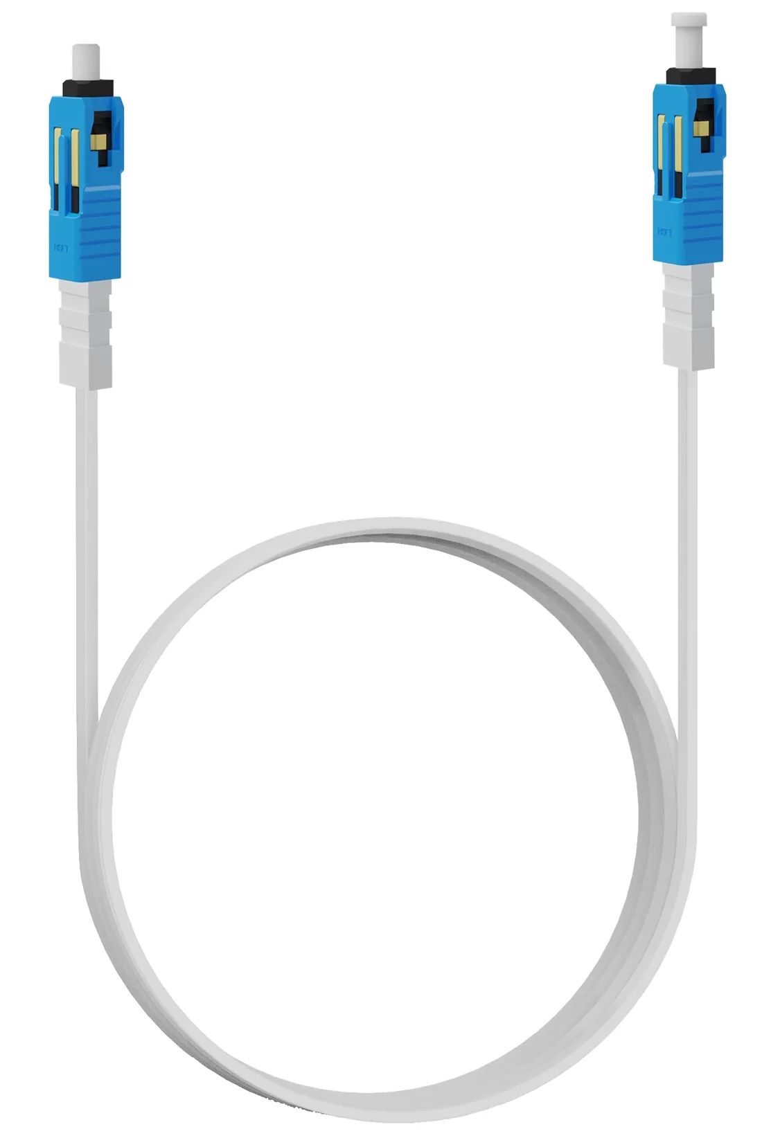
Hybrid PoF Cable
A flat hybrid cable with one G.657A2 fibre and a copper pair, terminated SC/UPC and supplied in 3, 20 or 50 m lengths. Attenuation is ≤0.4 dB/km at 1310 nm and ≤0.3 dB/km at 1550 nm; the jacket is rated −20 to +80 °C.
Updated October 24, 2026
- Fibre
- G.657A2, single core
- Attenuation
- ≤0.4 / ≤0.3 dB/km
- Lengths
- 3 / 20 / 50 m
- Temperature
- −20 to +80 °C
The short answer
What this product is specified for.
Included in the quotation
- Port count, connector polish and power configuration
- Model-level datasheet and test data
- Optical budget and splitter plan for the ODN
- Export packing, HS code and Incoterm
A hybrid PoF cable is not a patch cord with a power wire taped to it. It is a flat composite cable with one G.657A2 fibre in a tight sleeve, a copper pair, reinforcement and a PVC jacket, terminated with SC/UPC connectors. The fibre carries the PON signal; the copper pair carries 48 V DC to the PoF ONU. The flat profile (4.2 × 1.8 mm) fits behind ceiling tiles and through the same conduit as a normal drop cable.
The optical numbers are modest but important: ≤0.4 dB/km at 1310 nm and ≤0.3 dB/km at 1550 nm over a 1260–1626 nm range. A 50 m link therefore adds only about 0.02 dB of fibre loss; the connectors and the splitter dominate the budget. The G.657A2 bend-insensitive fibre tolerates the tight bends found above ceiling grids, which is why it is used instead of standard G.652D in this application.
Lengths are 3, 20 and 50 m as standard. Measure the actual route, including the drop from the ceiling void to the outlet and a 1 m service loop at each end; do not order by room size. The cable is rated −20 to +80 °C, so it can run in a ventilated riser or an outdoor enclosure that is protected from direct sun. For outdoor runs, add a UV-rated conduit and a drip loop.
Configuration table
The numbers that decide the fit.
Values are from the model datasheet. Where a value is model-dependent, the table says so instead of guessing.
| Parameter | Value |
|---|---|
| Fibre count | Single core |
| Fibre type | G.657A2 |
| Attenuation | ≤0.4 dB/km at 1310 nm; ≤0.3 dB/km at 1550 nm |
| Operating wavelength | 1260 – 1626 nm |
| Connector | SC/UPC |
| Lengths | 3 m / 20 m / 50 m |
| Operating temperature | −20 to +80 °C |
| Dimensions | 4.2 ± 0.2 mm (long axis); 1.8 ± 0.2 mm (short axis) |
Custom lengths and connector types are available on project quantities; confirm the bend radius and pulling tension before installation.
Engineering features
What changes on site.
One pull, two services
The fibre and the power pair are installed in one operation. There is no separate mains spur, conduit or socket at the ceiling.
Flat profile
4.2 × 1.8 mm fits behind ceiling tiles and through 20 mm conduit, with a bend-insensitive G.657A2 core.
Dielectric data path
The optical core is non-conductive. The power pair is separate; the cable does not create a copper Ethernet path into the ceiling.
Riser and outdoor cabinet
−20 to +80 °C covers a ventilated riser, a shaded outdoor cabinet and a ceiling void above a conditioned room.
Tested ends
Each assembly is terminated and tested. Record the insertion loss and the port number on the as-built label at both ends.
Standard lengths
3, 20 and 50 m cover a room, a floor and a warehouse bay. Custom lengths are quoted for project quantities.
Selection guide
Which configuration fits which site.
Start from the site, not from the model. The table is a starting point; the final check is the optical and power budget.
| Route | Length to order | Note |
|---|---|---|
| Ceiling AP, same room | 3 m | Include a 1 m service loop at the splitter |
| Corridor AP, same floor | 20 m | Measure along the cable tray, not the walking route |
| Warehouse bay / pole | 50 m | Add a drip loop and UV-rated conduit outdoors |
| Longer than 50 m | Custom / fibre + local PoE | Check the 200 m PoF power limit and voltage drop |
Do not coil excess cable tightly around the splitter; keep the bend radius above 20 mm and secure the cable with clips.
Applications
Where this product is used.
Related equipment
Complete the chain.
The product is quoted as part of a chain. These are the parts that usually travel with it.
Power over Fiber · access
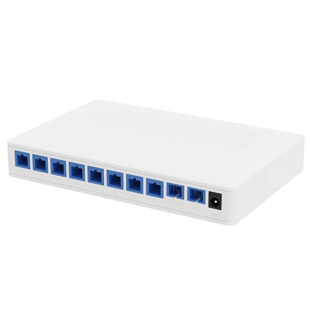
PoF Switch & PoF ONU
One hybrid cable to the ceiling: data and 12 W.
A Power-over-Fiber access set: an optical gateway, an 8-output PoF power splitter, hybrid PoF cable and a ceiling Wi-Fi 6 ONU. Each output delivers up to 12 W to 200 m, so ceiling APs and cameras run without a local mains socket.
- Power per port
- Up to 12 W
- Reach
- Up to 200 m
- Outputs
- 8 + 1 cascade
- Wi-Fi
- Wi-Fi 6 AX3000
Best for Outdoor Wireless Coverage · Campus Fibre Network · Parking Lot Camera System
View specificationsPower over Fiber · splitter
PoF Power Splitter
Eight outputs, 12 W each, one cascade port.
A 1×9 PoF power splitter that combines an optical splitter and a 48 V DC power distributor in one box. It feeds eight PoF ONUs at up to 12 W each to 200 m and provides a cascade port for a second splitter.
- Split
- 1×9 (8 + cascade)
- Output power
- ≤12 W per port
- Supply
- 48 V DC, 120 W
- Insertion loss
- ≤16.5 dB output
Best for Outdoor Wireless Coverage · Parking Lot Camera System · Bollard & Access Control Power
View specifications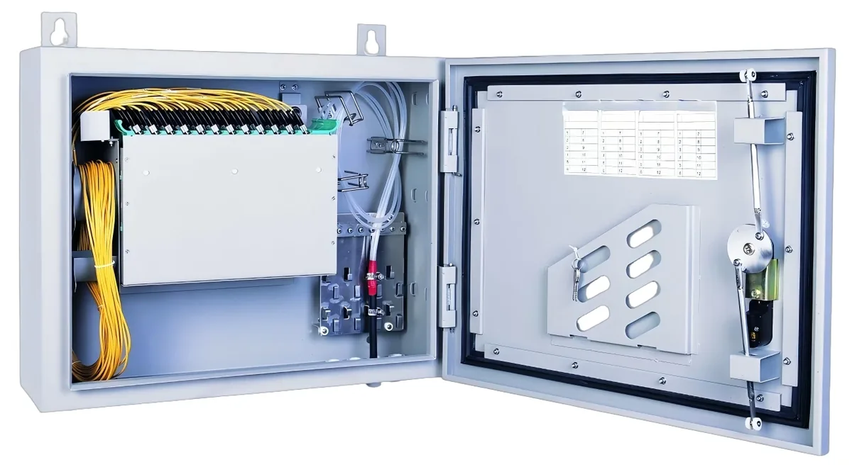
PON access · ODN
Fiber Optic Splitter (PLC)
1×2 to 1×64, SC/UPC or SC/APC.
Planar lightwave circuit splitters from 1×2 to 1×64 for PON ODN construction. Typical insertion loss runs from 3.6 dB at 1×2 to 20.5 dB at 1×64; each batch ships with test data and the connector polish you specify.
- Ratios
- 1×2 – 1×64
- Wavelength
- 1260 – 1650 nm
- Insertion loss
- 3.6 – 20.5 dB
- Connector
- SC/UPC / SC/APC
Best for FTTH Access Network · Campus Fibre Network · CCTV & Surveillance Power
View specifications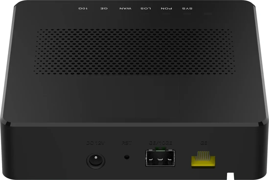
PON access · PoE ONU
PoE ONU & Reverse PoE
Power the ONU from the LAN, or the LAN from the ONU.
PoE ONU variants for corridors, rooms and MDUs: reverse-PoE (PD) units powered by a PoE switch, PSE units that power cameras and APs, and 4/8/24-port models for floor distribution. One XPON uplink, up to 24 PoE outputs.
- Uplink
- XPON / 10G PON
- PoE ports
- 1 – 24
- Modes
- PSE / PD
- Power
- 802.3af/at
Best for CCTV & Surveillance Power · Campus Fibre Network · Outdoor Wireless Coverage
View specificationsProduct FAQ
Hybrid PoF Cable: questions before the order.
If your question is not here, send the site details and we will answer with the calculation, not a brochure.
Ask an engineerCan I terminate this cable in the field?
The assembly is factory-terminated with SC/UPC connectors and tested. Field termination of hybrid cable is possible with a fusion splicer and mechanical power contacts, but it is slower and harder to test; order the length you need instead.
Does the copper pair carry Ethernet?
No. The copper pair carries 48 V DC only. Data travels on the fibre. The PoF ONU separates power and data at the far end.
What is the maximum length?
Standard assemblies go to 50 m. The PoF system is rated to 200 m per port, so longer custom lengths are possible, but voltage drop and optical loss must be calculated for the actual load.
Can it run outdoors?
The cable is rated −20 to +80 °C, but the jacket is not a substitute for UV protection. Run it in a UV-rated conduit, use a drip loop and protect the connectors in an IP-rated enclosure.
Is it compatible with standard SC/UPC patch panels?
The optical connector is SC/UPC, so it mates with standard SC/UPC adapters. The hybrid cable itself terminates at the PoF ONU or splitter; do not plug the power pair into a standard patch panel.
What bend radius should I keep?
Keep the long axis flat and avoid sharp folds. As a working rule, do not bend below 20 mm radius; the G.657A2 fibre tolerates tight bends, but the copper pair and jacket do not.
Next step
Need a Hybrid PoF Cable configuration checked?
Send the endpoint count, the longest run, the power condition and the destination. We reply with the configuration, the optical/power budget and the quotation assumptions.
No obligation. The plan states its assumptions so your engineer can check it.