
PON access · ODN
Fiber Optic Splitter (PLC)
Planar lightwave circuit splitters from 1×2 to 1×64 for PON ODN construction. Typical insertion loss runs from 3.6 dB at 1×2 to 20.5 dB at 1×64; each batch ships with test data and the connector polish you specify.
Updated October 24, 2026
- Ratios
- 1×2 – 1×64
- Wavelength
- 1260 – 1650 nm
- Insertion loss
- 3.6 – 20.5 dB
- Connector
- SC/UPC / SC/APC
The short answer
What this product is specified for.
Included in the quotation
- Port count, connector polish and power configuration
- Model-level datasheet and test data
- Optical budget and splitter plan for the ODN
- Export packing, HS code and Incoterm
A PLC splitter is the passive component that turns one PON port into many subscriber drops. The ratio is not a preference; it is an optical budget decision. A 1×64 splitter takes about 20.5 dB before any connector or splice, which leaves little margin on a 20 km link. A 1×32 at 16.5 dB leaves 4 dB more, often the difference between a stable link and a flapping ONU.
The table below gives the typical insertion loss and uniformity for standard PLC modules. These are industry-typical values; the actual batch test data is supplied with the order. Return loss is ≥55 dB for SC/UPC and ≥60 dB for SC/APC; directivity is ≥55 dB and polarisation-dependent loss is ≤0.2–0.3 dB depending on the ratio. The modules work from 1260 to 1650 nm, covering 1310/1490 nm PON and 1550 nm CATV overlay.
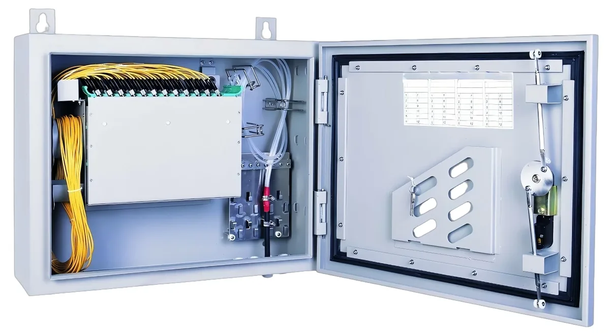
Mechanical format matters as much as the optical number. A bare module goes inside an ODF or a splice closure; a 1U rack panel puts 1×8 or 1×16 outputs in a telecom room; an ABS box is for a corridor or an outdoor cabinet. Keep the splitter ratio, connector polish and format on the same line of the BOM so the installer does not receive a 1×64 module for a 1×32 design.
Configuration table
The numbers that decide the fit.
Values are from the model datasheet. Where a value is model-dependent, the table says so instead of guessing.
| Ratio | Typical insertion loss | Typical uniformity | Typical use |
|---|---|---|---|
| 1×2 | ≤3.6 dB | ≤0.8 dB | Test point, small branch |
| 1×4 | ≤7.2 dB | ≤1.0 dB | Floor distribution |
| 1×8 | ≤10.5 dB | ≤1.2 dB | Building or small campus |
| 1×16 | ≤13.5 dB | ≤1.5 dB | Campus building, hotel |
| 1×32 | ≤16.5 dB | ≤2.0 dB | Estate, village, long span |
| 1×64 | ≤20.5 dB | ≤2.5 dB | Dense FTTH, short ODN |
Typical PLC values at 1310/1490/1550 nm. Confirm the ratio, connector and batch test data on the quotation.
Engineering features
What changes on site.
Ratio follows the budget
Choose the ratio after subtracting fibre, connector and splice loss from the OLT/ONU budget. Do not choose by subscriber count alone.
Uniform outputs
Low uniformity keeps the weakest port above the ONU sensitivity threshold, especially at 1×32 and 1×64.
Low reflectance
SC/APC (≥60 dB return loss) is preferred for CATV and long spans; SC/UPC (≥55 dB) is the standard for data PON.
Three formats
Bare module, ABS box and 1U rack panel. The format follows the enclosure and the number of outputs at that point.
Outdoor-ready options
Outdoor enclosures and hardened modules are quoted for pole or vault installation; confirm the IP rating and temperature range.
Batch test data
Each batch ships with insertion loss and return loss test data so the ODN as-built matches the design budget.
Selection guide
Which configuration fits which site.
Start from the site, not from the model. The table is a starting point; the final check is the optical and power budget.
| PON budget | Recommended split | Reason |
|---|---|---|
| 20 km, 1:64 | Not recommended without extra margin | 20.5 dB split leaves little for connectors and ageing |
| 20 km, 1:32 | 1×32 | 16.5 dB split leaves about 4 dB more margin |
| 10 km, 1:64 | 1×64 | Shorter span recovers the budget |
| In-building ODN | 1×64 or 1×32 | Short fibre and few splices |
| CATV overlay | 1×8 / 1×16 + SC/APC | Lower loss and better return loss for RF |
Use the actual OLT transmit power, ONU sensitivity and connector count; the table is a starting point, not a substitute for the calculation.
Integration
Where it sits in the chain.
The PON chain starts at the OLT port, passes through the splitter and the ODN, and ends at the ONU. The split ratio and the connector count decide the optical margin.
- One bill of materials for the whole chain
- Connector polish and PON mode confirmed before order
- Model-level test data supplied with the shipment
Related equipment
Complete the chain.
The product is quoted as part of a chain. These are the parts that usually travel with it.
PON access · OLT
GPON OLT
From a 1-PON gateway to a 112-PON headend.
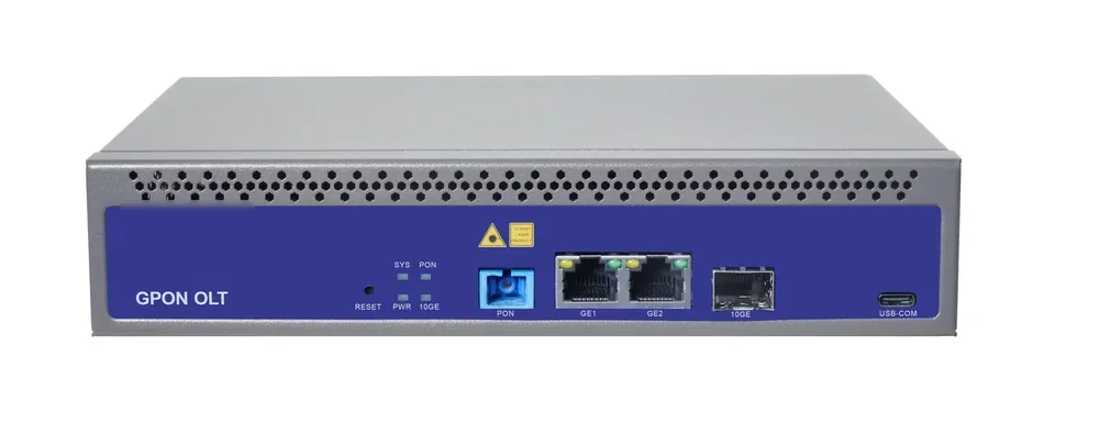
GPON OLT platforms for FTTH, campus and hotel access: 2.5 Gbps downstream and 1.25 Gbps upstream, 1:64 split per PON port and 20 km reach on Class B+ optics. Configurations run from a compact 1-PON gateway with built-in AC to a chassis with up to 112 PON ports.
- Line rate
- 2.5 Gbps ↓ / 1.25 Gbps ↑
- Max split
- 1:64 per PON port
- Reach
- 20 km, Class B+
- PON ports
- 1 – 112
Best for FTTH Access Network · Campus Fibre Network · Outdoor Wireless Coverage
View specifications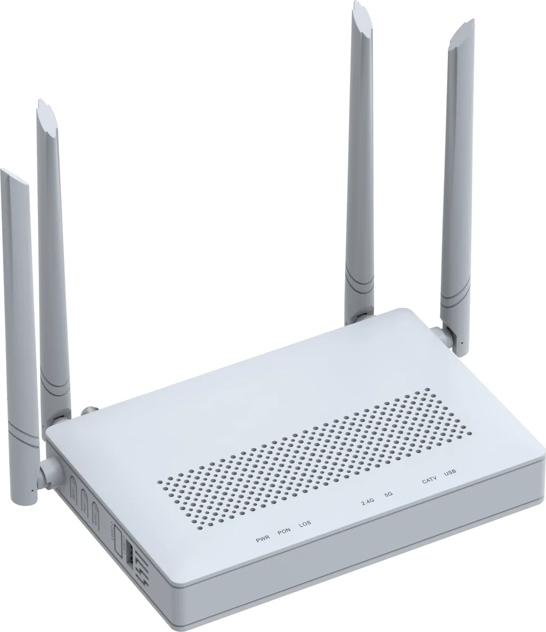
PON access · ONU / ONT
GPON / XPON ONU & ONT
From a 1-GE bridge to a 4-GE Wi-Fi 6 gateway.
XPON ONU and ONT options for FTTH, hotel rooms, offices and outdoor cabinets: 1, 2 or 4 GE ports, Wi-Fi 4/5/6, CATV and POTS options, and 10G PON models. All units are SC single-mode, 20 km, EPON/GPON dual-mode where the model supports it.
- PON
- XPON, EPON/GPON
- User ports
- 1 – 4 × GE
- Wi-Fi
- Wi-Fi 4 / 5 / 6
- Reach
- 20 km
Best for FTTH Access Network · Campus Fibre Network · Outdoor Wireless Coverage
View specifications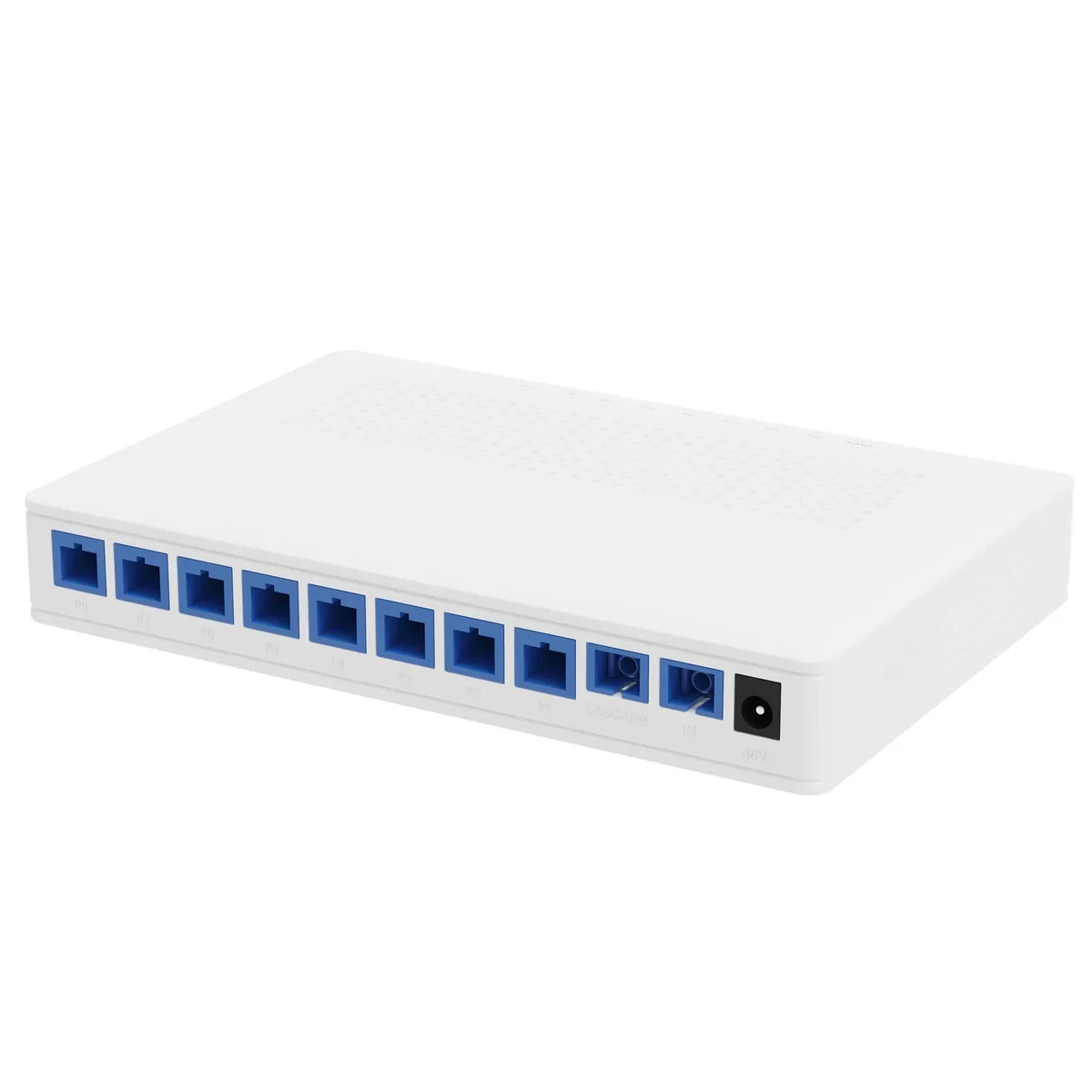
Power over Fiber · splitter
PoF Power Splitter
Eight outputs, 12 W each, one cascade port.
A 1×9 PoF power splitter that combines an optical splitter and a 48 V DC power distributor in one box. It feeds eight PoF ONUs at up to 12 W each to 200 m and provides a cascade port for a second splitter.
- Split
- 1×9 (8 + cascade)
- Output power
- ≤12 W per port
- Supply
- 48 V DC, 120 W
- Insertion loss
- ≤16.5 dB output
Best for Outdoor Wireless Coverage · Parking Lot Camera System · Bollard & Access Control Power
View specifications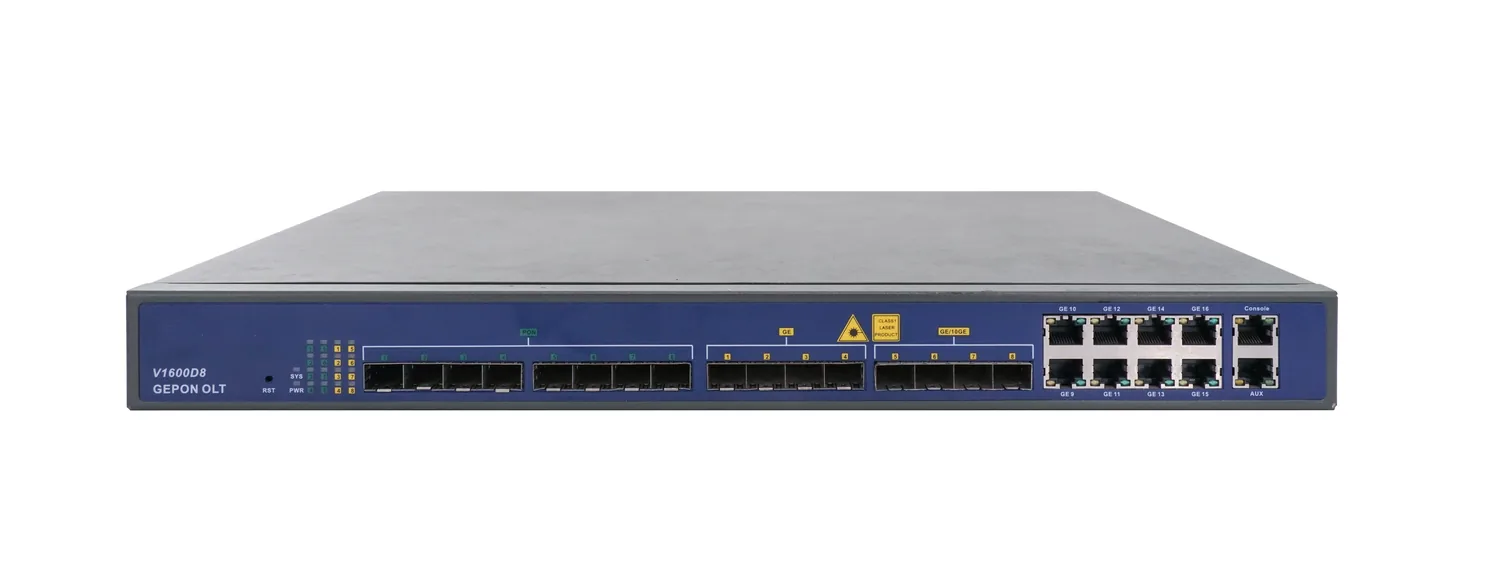
PON access · OLT
8-Port EPON OLT
1U, eight EPON ports, up to 512 ONUs.
A 1U EPON OLT with eight PON ports, 16 uplink ports and a 128 Gbps backplane. It supports 1:64 splitting, 20 km reach and up to 512 ONUs, making it a compact headend for CCTV, campus and small FTTH networks.
- PON ports
- 8 × EPON
- Line rate
- 1.25 Gbps symmetric
- Max ONUs
- 512 (64 per port)
- Backplane
- 128 Gbps
Best for CCTV & Surveillance Power · Campus Fibre Network · FTTH Access Network
View specificationsProduct FAQ
Fiber Optic Splitter (PLC): questions before the order.
If your question is not here, send the site details and we will answer with the calculation, not a brochure.
Ask an engineerWhat is the insertion loss of a 1×64 splitter?
About 20.5 dB typical, before connectors and splices. That is a theoretical 18 dB split loss plus excess loss. On a 20 km PON, 1×64 is often too aggressive; 1×32 (16.5 dB) is safer.
UPC or APC?
SC/UPC for standard data PON; SC/APC for CATV overlay and long spans because the angled polish gives ≥60 dB return loss. Do not mix polish types without a hybrid patch cord.
Can I cascade two splitters?
Yes, but the losses add. A 1×8 followed by a 1×8 gives 1×64 with about 21 dB plus an extra connector pair. Calculate the total and keep a 3 dB ageing margin.
Where should the splitter be installed?
At the ODF or in a street cabinet for the first stage, and in a building box or corridor enclosure for the second stage. Keep the splitter accessible for testing and cleaning.
Do you supply the enclosure?
Yes. Bare modules, ABS boxes, rack panels and outdoor enclosures are quoted with the splitter so the format matches the installation point.
How do I clean the connectors?
Use a one-click cleaner and inspect with a scope. A dirty SC connector can add 1–3 dB and cause intermittent ONU drops; cleaning is part of commissioning, not an afterthought.
Next step
Need a Fiber Optic Splitter (PLC) configuration checked?
Send the endpoint count, the longest run, the power condition and the destination. We reply with the configuration, the optical/power budget and the quotation assumptions.
No obligation. The plan states its assumptions so your engineer can check it.