What is the difference between PoF and PoE?
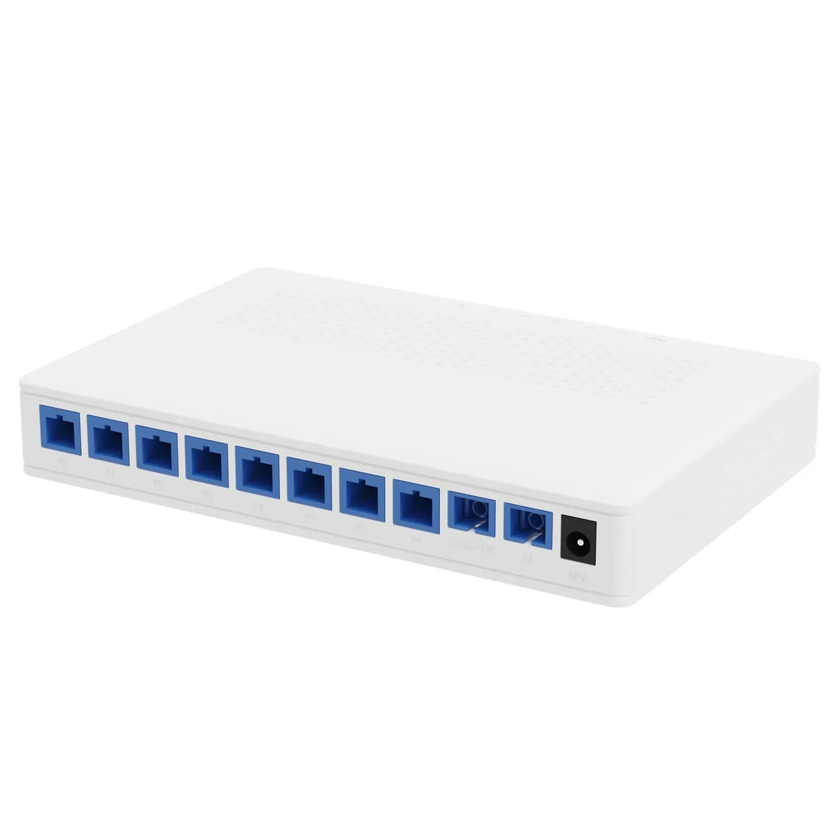
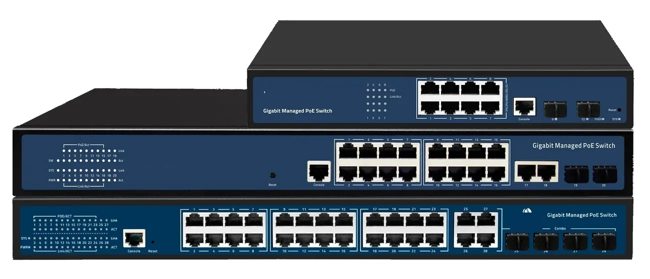
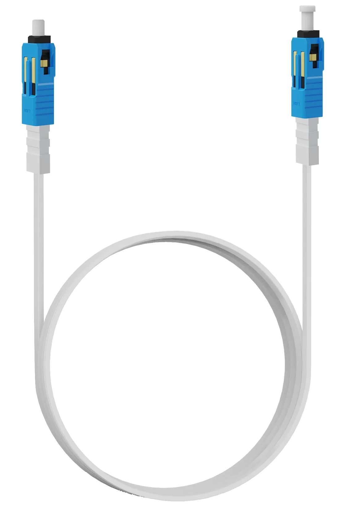
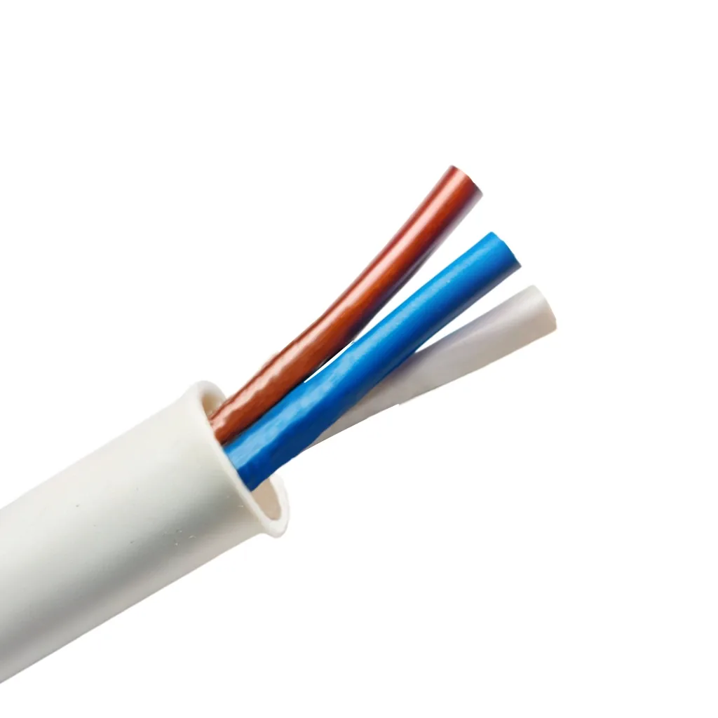
PoE sends DC power over the same twisted pairs that carry Ethernet. It is standardized in IEEE 802.3af/at/bt and limited to a 100 m channel. PoF, as used here, sends DC power over a separate copper pair inside a hybrid cable that also contains an optical fibre. The data travels on the fibre, the power on the copper, and the link can reach 200 m. PoF is not an IEEE Ethernet standard; it is a system-level design with its own splitter, cable and ONU.
That difference decides the use case. PoE is the default for devices within 100 m of a powered switch. PoF is for devices beyond 100 m, or at a location where a mains socket is absent or expensive to install.
| Attribute | PoE | PoF (hybrid cable) |
|---|---|---|
| Data path | Copper Ethernet pairs | Optical fibre |
| Power path | Same copper pairs | Separate copper pair in the hybrid cable |
| Standard | IEEE 802.3af/at/bt | System design, not an IEEE PoE mode |
| Reach | 100 m channel | Up to 200 m per port |
| Power per port | 15.4 / 30 / 60 / 90 W at source | Up to 12 W per port |
| Endpoint mains | Switch needs mains | Not required |
| Surge path | Copper data + power | Optical data; copper power pair only |
When is PoF the better choice?
When the endpoint is 100–200 m from the nearest power source, draws under 12 W, and a mains spur would require trenching, conduit or an electrician. Ceiling APs, fixed cameras on poles, card readers, intercoms and sensors are the typical loads. The PoF splitter sits in a powered cabinet; the hybrid cable runs to the device.
It is also a good fit where the copper data path is the surge risk. The fibre is dielectric, so the data link does not bring a metallic path to the pole. The power pair still needs protection, but the exposure is shorter and the data path is isolated.
When is PoF the wrong choice?
When the load exceeds 12 W per port, when the run exceeds 200 m, or when the device needs a standard PoE handshake or a high power class. A PTZ camera with a heater, a 60 W access point, a display or a bollard motor is not a 12 W load. Use a local PoE switch, a mains feed, or a different power architecture.
It is also the wrong choice when the site already has a powered cabinet within 100 m. In that case, a standard PoE switch is cheaper, more familiar and easier to service. PoF is a solution to a specific distance/power problem, not a universal replacement for PoE.
| Load | PoE | PoF | Better choice |
|---|---|---|---|
| Fixed camera, 8 W, 60 m | Yes | Possible | PoE (cheaper) |
| Fixed camera, 8 W, 160 m, no mains | No | Yes | PoF |
| Wi-Fi 6 AP, 12 W, 120 m | No | At the limit | PoF with 20% headroom |
| PTZ with heater, 30 W | Yes within 100 m | No | Local PoE switch |
| Card reader, 8 W, 150 m | No | Yes | PoF |
How do you design a mixed PoE + PoF site?
Keep the two power domains separate. A PoE switch feeds the copper group; a PoF splitter feeds the no-mains group. Both can uplink to the same OLT or core switch, but do not parallel the 48 V rails or assume the PoE budget covers the PoF load.
Label the splitter ports and the switch ports with the same device names. In a fault, the first question is which power domain the device belongs to; a clear label saves a site visit. Keep a spare splitter and a spare PoE switch on site for critical groups.
- Separate PoE and PoF power domains.
- One uplink plan, two power plans.
- Label by device, not by port number alone.
- Keep 20% headroom on both budgets.
- Spare splitter and switch for critical groups.
Is PoF more expensive than PoE?
The cable and splitter cost more than a copper patch cord and a PoE port. The saving is the mains spur: conduit, cable, socket, electrician, weatherproof box and surge protection. On a pole 150 m from the building, the installed cost of a mains spur often exceeds the PoF hardware. On a ceiling 20 m from a switch, PoE is cheaper.
Compare installed cost, not unit price. A PoF design also changes the maintenance model: the splitter is a single powered point for eight devices, which is easier to service than eight local sockets but is also a single point of failure for those eight. Add a spare or a second splitter for critical sites.
Use this on a real site
Send the endpoint count, the longest run, the mains condition and the load. We will apply this calculation to your project and return the optical/power budget with the bill of materials.