
How far can PoE run?
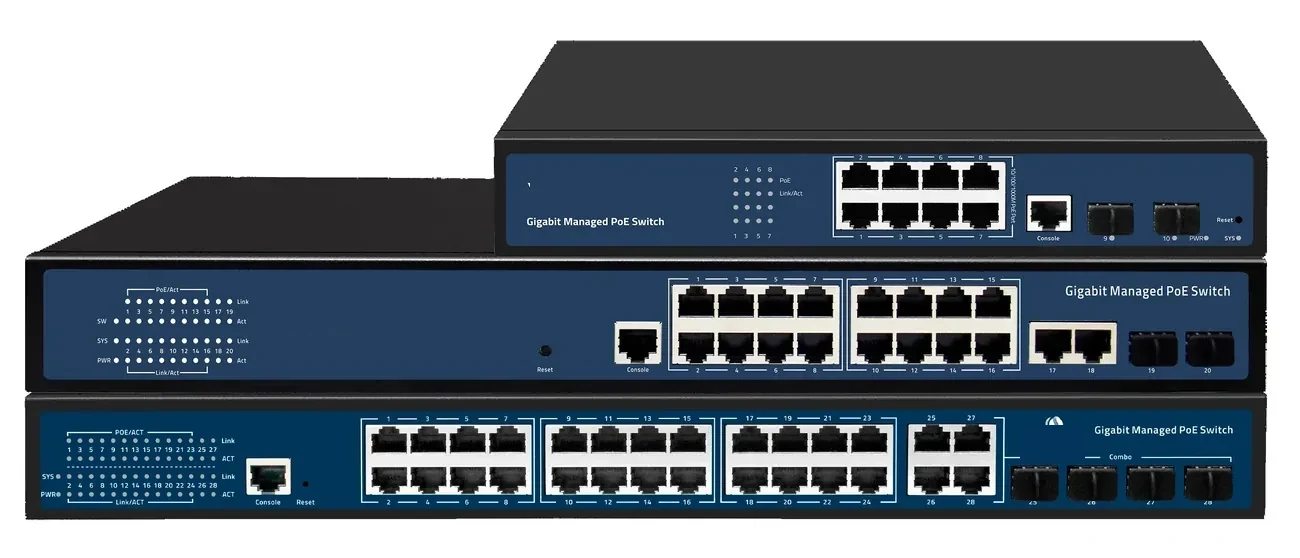
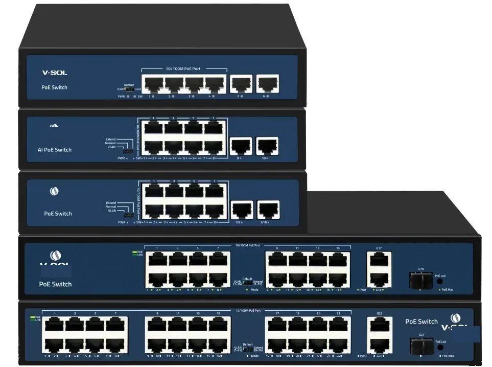
One hundred metres. That is the channel limit in IEEE 802.3 for 10/100/1000BASE-T over twisted-pair copper, and it includes the horizontal cable plus both patch cords. The limit applies to the data link; PoE adds power on the same pairs but does not extend the data reach. A PoE switch rated for 250 m is not a standard Ethernet port, or it is using an extender or a proprietary mode.
The number is often misread as “100 m of cable in the ceiling.” In practice the permanent link is limited to 90 m and the two patch cords together to 10 m. If the ceiling run is 95 m and the cabinet patch is 5 m, the channel is already at the limit before the far patch cord is counted.
- Channel = horizontal cable + both patch cords; 100 m total.
- Permanent link ≤ 90 m; patch cords ≤ 10 m combined.
- Cat5e, Cat6, Cat6a, Cat7 and Cat8 all use a 100 m channel for Ethernet.
- PoE (802.3af/at) and PoE++ (802.3bt) do not change the 100 m limit.
Does Cat6 or Cat6a run farther than Cat5e?
No for Ethernet distance. Category changes bandwidth and noise performance, not the 100 m channel. Cat6 supports 10GBASE-T to 55 m (or 100 m with careful installation and limited alien crosstalk); Cat6a supports 10GBASE-T to 100 m. Cat7 and Cat8 are shielded solutions with the same 100 m channel for the Ethernet rates they support. None of them gives a 200 m PoE link.
Category does matter for power. A larger conductor (23 AWG vs 24 AWG) has lower resistance and therefore less voltage drop at the same current. That is why a 30 W load at 100 m can see a noticeably lower voltage on a thin, high-resistance cable, especially in a hot bundle. The device may still power up, but it is closer to its undervoltage threshold.
| Cable | Ethernet distance | Effect on PoE |
|---|---|---|
| Cat5e | 100 m | Adequate for 802.3af/at; higher voltage drop on long runs |
| Cat6 | 100 m (10GBASE-T to 55 m) | Lower resistance than some Cat5e; check AWG |
| Cat6a | 100 m (10GBASE-T to 100 m) | Better for 10G and higher-power PoE; shielded options |
| Cat7 / Cat8 | 100 m for supported rates | Not a distance extension; shielding needs proper bonding |
Distance is a channel limit. Category changes bandwidth and loss, not the 100 m rule.
Why does a 30 W camera fail at 90 m?
Because the cable is a resistor. At 30 W and 48 V, the current is about 0.63 A. A 100 m loop of 24 AWG copper has roughly 20 Ω of resistance, so the round trip drops about 12.6 V. The camera sees about 35 V, not 48 V. If its input range is narrow or the cable is warm (resistance rises with temperature), it may reset when the IR LEDs or the heater turn on.
The calculation is simple: Vdrop = I × Rloop, where Rloop is the resistance of both conductors. Use the conductor resistance from the cable datasheet, double it for the loop, multiply by the device current, and subtract from the PSE voltage. Then check the device’s minimum input voltage, not its nominal 48 V.
- 30 W at 48 V ≈ 0.63 A; 90 W at 48 V ≈ 1.88 A.
- Voltage drop grows linearly with current and length.
- Heat raises conductor resistance; a bundled cable runs hotter.
- Check the device’s minimum input voltage, not only its wattage.
How do you reach 200–500 m?
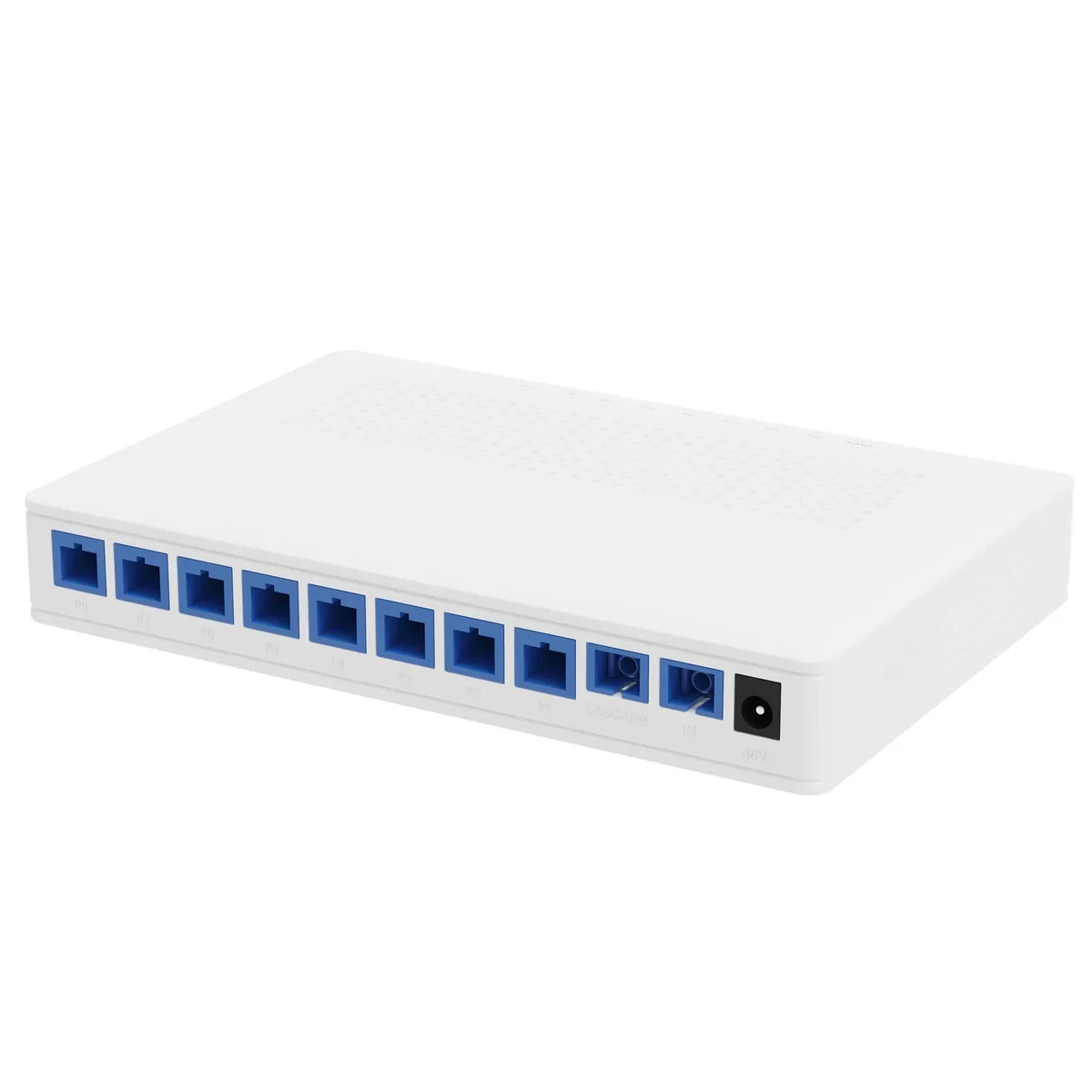
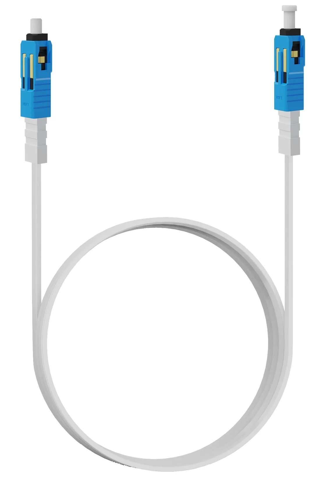
There are three practical paths. A PoE extender repeats the Ethernet and PoE signal, adding another 100 m per hop; it needs power at the mid-point, which is often the same problem moved down the cable. A fibre link with a local PoE switch removes the distance limit entirely, but needs a powered cabinet at the far end. Power over Fiber (PoF) sends data and up to 12 W over a hybrid cable to 200 m, with no mains at the endpoint.
The right choice depends on the load and the site. A 10 W camera at 180 m with no mains is a PoF case. A 60 W PTZ at 300 m needs a local cabinet with a PoE switch or a mains feed, because 60 W is outside the 12 W PoF port rating. A cluster of eight cameras at 250 m is usually cheaper on fibre plus a local switch than on eight PoF runs.
| Path | Reach | Endpoint power | Mains at endpoint | Best for |
|---|---|---|---|---|
| Copper PoE | 100 m channel | 15.4 / 30 W at source | Switch needs mains | Devices near a powered cabinet |
| PoE extender | 100 m per hop; 200–500 m typical | Reduced by each hop | Yes, at each extender | Retrofit with a powered mid-point |
| Power over Fiber | Up to 200 m | Up to 12 W per port | No | Ceiling APs, pole cameras, readers |
| Fibre + local PoE switch | PON 20 km; local copper 100 m | Local switch budget | Yes, at the local cabinet | Clusters and higher loads |
What should you measure before choosing a path?
Measure the route, not the room. Include the vertical drop, the cable tray, the service loop and both patch cords. Record the device’s nominal and peak current, its minimum input voltage and whether it has a heater or IR illuminator. Then check whether mains is present at the endpoint and whether the nearest cabinet has space and power for a switch.
A one-page table with distance, load, mains and device count is enough to choose the path. If the answer is still ambiguous, the tie-breaker is usually maintenance: a local switch adds a powered cabinet to service; a PoF drop adds a splitter port but no local power.
- Route length including drops, tray and service loops.
- Device nominal and peak watts; minimum input voltage.
- Mains present at the endpoint?
- Nearest cabinet: space, power, uplink and cooling.
- Surge exposure along the copper route.
Use this on a real site
Send the endpoint count, the longest run, the mains condition and the load. We will apply this calculation to your project and return the optical/power budget with the bill of materials.