What is the insertion loss of each splitter ratio?
A splitter divides optical power, and the theoretical loss is 10 × log10(N). A 1:2 split loses 3 dB, 1:4 loses 6 dB, 1:8 loses 9 dB, 1:16 loses 12 dB, 1:32 loses 15 dB and 1:64 loses 18 dB. Real PLC modules add excess loss, so the typical values are 3.6, 7.2, 10.5, 13.5, 16.5 and 20.5 dB.
The difference between theoretical and typical is the excess loss, and it grows with the ratio. That is why a 1:64 splitter is not “18 dB” on a quote; it is about 20.5 dB, before connectors and splices. On a long ODN, that 2.5 dB matters.
| Ratio | Theoretical loss | Typical insertion loss | Typical uniformity |
|---|---|---|---|
| 1:2 | 3.0 dB | ≤3.6 dB | ≤0.8 dB |
| 1:4 | 6.0 dB | ≤7.2 dB | ≤1.0 dB |
| 1:8 | 9.0 dB | ≤10.5 dB | ≤1.2 dB |
| 1:16 | 12.0 dB | ≤13.5 dB | ≤1.5 dB |
| 1:32 | 15.0 dB | ≤16.5 dB | ≤2.0 dB |
| 1:64 | 18.0 dB | ≤20.5 dB | ≤2.5 dB |
Typical PLC values. Batch test data is supplied with the order.
How do you choose a ratio from the optical budget?
Start with the OLT transmit power and the ONU sensitivity. For a Class B+ GPON link, the budget is about 28 dB. Subtract the splitter loss, the fibre loss (0.35 dB/km at 1310 nm), the connector loss (0.3–0.5 dB per pair), the splice loss (0.1 dB each) and a 3 dB ageing margin. The remainder must be ≥ 0.
If the remainder is negative, reduce the split ratio, shorten the span, or move the splitter closer to the subscriber. Do not add an amplifier to a PON; it is a passive optical network. A 1:32 split is often the right answer for a 20 km span; 1:64 for a short in-building ODN.
- Budget = OLT TX − ONU sensitivity.
- Subtract splitter, fibre, connectors, splices.
- Keep a 3 dB ageing margin.
- If negative, reduce the split or the distance.
Why does uniformity matter?
Uniformity is the spread between the strongest and weakest output. A 1:64 splitter with ±2.5 dB uniformity means the weakest port can be 5 dB below the strongest. If the design margin is 3 dB, the weakest subscriber may be outside the budget while the average looks fine.
For long spans or high split ratios, ask for the per-port test data, not only the typical value. Connect the weakest port to the longest drop if the design is tight; or use a lower ratio.
UPC or APC, and where should the splitter sit?
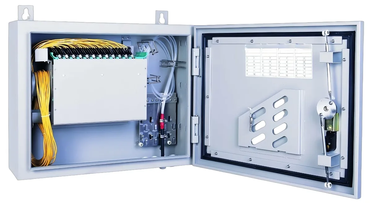
SC/UPC is standard for data PON; SC/APC is preferred for CATV overlay and long spans because the angled polish gives ≥60 dB return loss. Do not mix polish types without a hybrid patch cord. The splitter can be a bare module in an ODF, an ABS box in a corridor, or a 1U rack panel in a telecom room.
Put the first splitter at the ODF or a street cabinet, and the second stage in the building. Keep it accessible for testing and cleaning. A splitter buried in a sealed ceiling box is a maintenance problem.
Can you cascade splitters?
Yes, but the losses add. A 1:8 followed by a 1:8 gives 1:64 with about 21 dB plus an extra connector pair. Cascading is useful when the first stage is in a street cabinet and the second stage is in a building, but it must be in the budget from the start.
Do not cascade 1:64 + 1:64; that is 1:4096 and far beyond a PON port’s ONU limit. The OLT port also has a maximum ONU count, typically 64 or 128, which caps the practical split regardless of the optical budget.
| Stage 1 | Stage 2 | Combined | Typical splitter loss | Typical layout |
|---|---|---|---|---|
| 1:2 | 1:32 | 1:64 | ≈20.1 dB | Headend + street cabinet |
| 1:4 | 1:16 | 1:64 | ≈20.7 dB | Cabinet + building |
| 1:8 | 1:8 | 1:64 | ≈21.0 dB | Cabinet + floor |
| 1:4 | 1:8 | 1:32 | ≈17.7 dB | Two-stage in-building ODN |
Add 0.3–0.5 dB per mated connector pair and include the second-stage splitter in the optical budget.
Use this on a real site
Send the endpoint count, the longest run, the mains condition and the load. We will apply this calculation to your project and return the optical/power budget with the bill of materials.