ODN engineering

Optical Link Budget:
The Calculation Behind a Working PON

A step-by-step PON link budget with transmit power, splitter loss, fibre loss, connectors, splices and ageing margin — plus a worked 20 km example.

Guanheng Engineering Desk October 24, 2026 7 min read
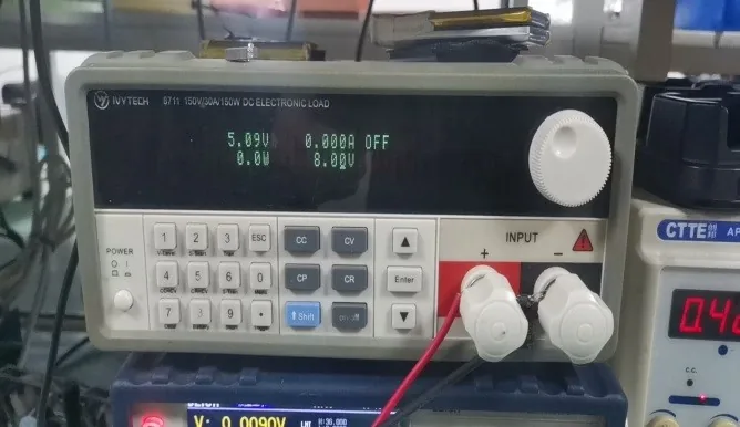
Power and optical test bench

What is the PON link budget formula?

The link budget is the difference between the OLT transmit power and the ONU receiver sensitivity. Every passive element between them subtracts from that budget: the splitter, the fibre, the connectors, the splices and any WDM coupler. The result must be greater than zero, with an ageing margin.

Budget = (OLT TX power) − (ONU RX sensitivity). Available margin = Budget − splitter loss − fibre loss − connector loss − splice loss − WDM loss. Require available margin ≥ 3 dB.

ElementTypical lossNotes
OLT TX power+4.5 to +9 dBm (EPON example)From the OLT datasheet
ONU RX sensitivity−27 dBm (XPON example)From the ONU datasheet
1:32 PLC splitter16.5 dB1:64 is about 20.5 dB
Fibre 1310 nm0.35 dB/km0.2 dB/km at 1550 nm
Connector pair0.3 – 0.5 dBPer mated pair; count both ends
Splice0.1 dBPer splice
Ageing margin3 dBDo not design to zero

What does a 20 km GPON budget look like?

Take a Class B+ GPON OLT with +3 dBm transmit power and an ONU sensitivity of −27 dBm. Budget = 3 − (−27) = 30 dB. A 1:32 splitter takes 16.5 dB, 20 km of fibre at 0.35 dB/km takes 7 dB, six connector pairs at 0.4 dB take 2.4 dB, and four splices at 0.1 dB take 0.4 dB. Total = 26.3 dB. Margin = 30 − 26.3 = 3.7 dB, which passes with the 3 dB ageing reserve.

Change the splitter to 1:64 (20.5 dB) and the total becomes 30.3 dB, leaving −0.3 dB. The link fails. The fix is a 1:32 splitter, a shorter span, fewer connectors, or a higher-power OLT optic. This is why the split ratio is the first thing to check, not the last.

ItemCalculationBudget remaining
Class B+ budget3 − (−27)30.0 dB
1:32 splitter−16.5 dB13.5 dB
20 km fibre at 0.35 dB/km−7.0 dB6.5 dB
6 connector pairs at 0.4 dB−2.4 dB4.1 dB
4 splices at 0.1 dB−0.4 dB3.7 dB
Ageing reserve−3.0 dB0.7 dB pass

A 1:64 splitter adds 20.5 dB instead of 16.5 dB and leaves −0.3 dB: the link fails.

What should you measure in the field?

Measure the OLT output power with a calibrated power meter, then measure at the ONU input. The difference is the actual path loss. Compare it with the calculated value; a 2–3 dB discrepancy usually means a dirty connector, a bad splice, a wrong splitter or a macrobend.

Record the values per port on the as-built. A baseline lets the next technician see whether a link has degraded. Clean and inspect every connector before measuring; a dirty SC connector can add 1–3 dB and look like a splitter problem.

Why keep a 3 dB ageing margin?

Laser output drops with age and temperature, connectors degrade with mating cycles, and splices can drift. A design that works at 0 dB margin on day one will fail in year three. The 3 dB margin is a practical allowance for ageing, temperature and repair splices.

If the site has a high temperature swing or many field connectors, use 4–5 dB. If the margin is below 3 dB, reduce the split ratio or move the splitter; do not rely on a higher-power ONU alone.

How does a CATV overlay change the budget?

A 1550 nm CATV signal shares the ODN with the PON. The WDM coupler adds loss (typically 0.5–1.5 dB), and the CATV receiver has its own input range (+2 to −18 dBm). The PON budget and the CATV budget must both pass; a link that works for data may be too lossy for the RF channel.

Plan the two budgets separately, then combine them at the headend. If the CATV receiver is at the edge of its range, add an EDFA or reduce the split; do not boost the PON laser to compensate.

Use this on a real site

Send the endpoint count, the longest run, the mains condition and the load. We will apply this calculation to your project and return the optical/power budget with the bill of materials.
Article FAQ

What questions does this guide usually raise?

If your question is not here, send the site details and we will answer with the calculation, not a brochure.

Ask an engineer

What is a good optical margin?

At least 3 dB after all losses, preferably 4–5 dB on outdoor or high-temperature sites. Designing to 0 dB leaves no room for ageing, cleaning or repair splices.

How much loss does a connector add?

A mated SC/UPC pair is typically 0.3–0.5 dB. Count every pair: OLT to ODF, ODF to splitter, splitter to ODF, ODF to ONU. A link with six pairs can lose 2–3 dB before the fibre.

How much loss per kilometre?

About 0.35 dB/km at 1310 nm and 0.2 dB/km at 1550 nm for standard single-mode fibre. Use the cable datasheet for the actual value.

What is the budget of a Class B+ GPON?

About 28 dB (for example, +1.5 dBm transmit and −27 dBm sensitivity, or +3 and −25). Always use the actual OLT and ONU datasheet values, not the class headline.

Can I use a higher-power ONU to fix a bad budget?

The ONU receiver sensitivity is fixed; a higher-power OLT optic or a lower split ratio is the usual fix. A higher-power ONU transmit helps the upstream, not the downstream budget.

Why does the link work on the bench but fail in the field?

The bench has short fibre and few connectors. The field adds splitters, splices, patch panels, bends and temperature. Measure the actual path loss and compare it with the design; the difference is usually a connector or a splitter.

Equipment in this design

The parts this guide refers to.

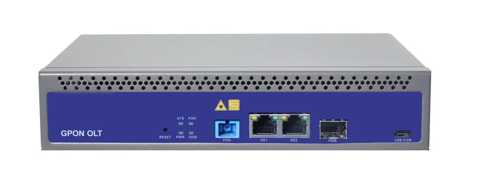
01GPON OLT with multiple PON ports and SFP uplinks

PON access · OLT

GPON OLT

From a 1-PON gateway to a 112-PON headend.

GPON OLT platforms for FTTH, campus and hotel access: 2.5 Gbps downstream and 1.25 Gbps upstream, 1:64 split per PON port and 20 km reach on Class B+ optics. Configurations run from a compact 1-PON gateway with built-in AC to a chassis with up to 112 PON ports.

Line rate
2.5 Gbps ↓ / 1.25 Gbps ↑
Max split
1:64 per PON port
Reach
20 km, Class B+
PON ports
1 – 112

Best for FTTH Access Network · Campus Fibre Network · Outdoor Wireless Coverage

View specifications
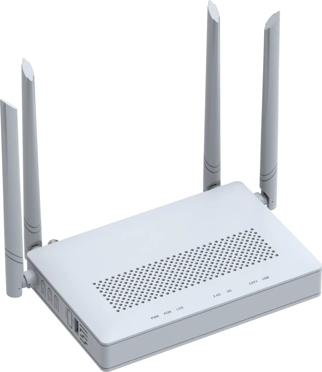
02XPON ONT with four GE ports, Wi-Fi 6 antennas and USB

PON access · ONU / ONT

GPON / XPON ONU & ONT

From a 1-GE bridge to a 4-GE Wi-Fi 6 gateway.

XPON ONU and ONT options for FTTH, hotel rooms, offices and outdoor cabinets: 1, 2 or 4 GE ports, Wi-Fi 4/5/6, CATV and POTS options, and 10G PON models. All units are SC single-mode, 20 km, EPON/GPON dual-mode where the model supports it.

PON
XPON, EPON/GPON
User ports
1 – 4 × GE
Wi-Fi
Wi-Fi 4 / 5 / 6
Reach
20 km

Best for FTTH Access Network · Campus Fibre Network · Outdoor Wireless Coverage

View specifications
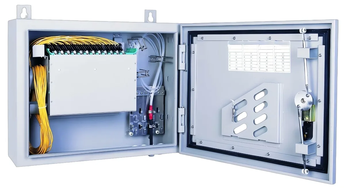
03Fiber distribution box with PLC splitters and SC adapters

PON access · ODN

Fiber Optic Splitter (PLC)

1×2 to 1×64, SC/UPC or SC/APC.

Planar lightwave circuit splitters from 1×2 to 1×64 for PON ODN construction. Typical insertion loss runs from 3.6 dB at 1×2 to 20.5 dB at 1×64; each batch ships with test data and the connector polish you specify.

Ratios
1×2 – 1×64
Wavelength
1260 – 1650 nm
Insertion loss
3.6 – 20.5 dB
Connector
SC/UPC / SC/APC

Best for FTTH Access Network · Campus Fibre Network · CCTV & Surveillance Power

View specifications
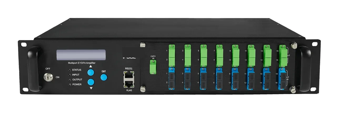
04Rack-mount EDFA optical amplifier with status display

Optical transmission · 1550 nm

EDFA & 1550 nm Transmitter

CATV overlay and long-haul 1550 nm transport.

1550 nm optical transmitters and erbium-doped fibre amplifiers for CATV overlay and long-distance transport: direct-modulated 10 dBm and external-modulated 7/9 dBm transmitters, plus 4/8/16/32-port EDFA units at 19/22 dBm.

Wavelength
1550 nm
EDFA ports
4 / 8 / 16 / 32
Output power
19 / 22 dBm
Transmitter
7 / 9 / 10 dBm

Best for Campus Fibre Network · FTTH Access Network

View specifications

Next step

Turn this guide into a bill of materials.

We apply the same calculation to your site and return the split ratio, the PoE/PoF load and the assumptions used.

No obligation. The plan states its assumptions so your engineer can check it.