
Why use 1550 nm for CATV overlay and long transport?
The 1550 nm window has lower fibre loss than 1310 nm, about 0.2 dB/km instead of 0.35 dB/km, and it supports erbium-doped fibre amplification. That combination lets one transmitter feed a passive split and an EDFA chain without regenerating the RF signal. On a hotel or campus, the CATV headend sits beside the OLT; a WDM coupler combines 1550 nm CATV with 1490/1310 nm PON, and an ONU with a CATV port separates it at the room.
The overlay is not automatic. The splitter and connectors must pass all three windows, the CATV receiver must accept the optical input, and the RF level must stay inside the receiver AGC range. The EDFA and 1550 nm transmitter page covers the transmitter, amplifier and receiver family; the CATV optical receiver page covers the subscriber end.
Direct or external modulation: which transmitter fits?
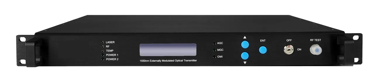
A direct-modulated transmitter modulates the laser current. It is simple and economical, which is why a 10 dBm unit is common in a small headend with a short span. It also has chirp and stimulated Brillouin scattering (SBS) limits, so it is not the best choice for a long span or a high-power EDFA launch.
An externally modulated transmitter uses a separate modulator, giving lower chirp and better performance over long spans or high launch power. The 7/9 dBm external units cost more, but they leave a cleaner margin. Match the transmitter to the span and the EDFA input, not to the highest output number in the catalogue. The 1550 nm transmitter page lists the direct and external options.
| Transmitter | Output | Typical span | Best fit | Watch-out |
|---|---|---|---|---|
| Direct-modulated | 10 dBm | Short headend span | Small CATV overlay | Chirp and SBS limits |
| External-modulated | 7 / 9 dBm | Longer span | Campus / district | Higher cost, better margin |
| EDFA 19 dBm | 4/8/16/32 ports | Distribution after the transmitter | Multi-building CATV | Input power and gain |
| EDFA 22 dBm | 4/8/16/32 ports | Long haul / high split | District headend | Receiver input range |
Output power and port count are model-specific. Confirm the input range, gain and connector on the datasheet.
What does an EDFA add to the link?
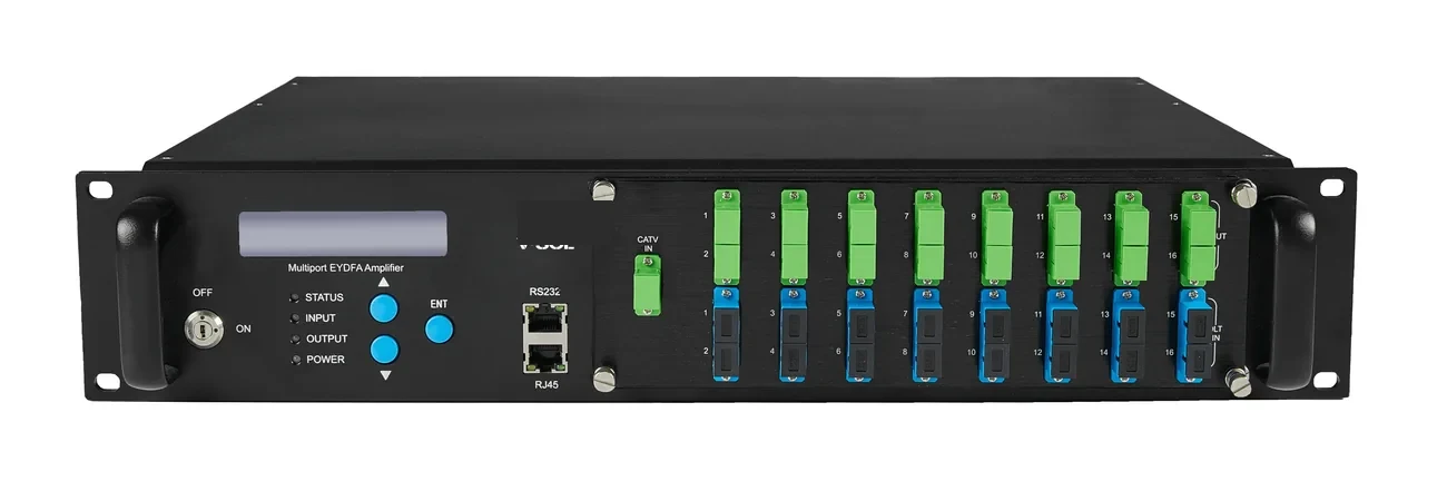
An EDFA amplifies the 1550 nm optical signal before the split, so one transmitter can serve more buildings or floors. The amplifier does not create RF capacity; it restores optical power lost in the split and the fibre. The output is divided by the splitter, and each output must still land inside the receiver input window.
The EDFA family covers 4, 8, 16 and 32 output ports at 19 or 22 dBm. More ports mean more splits, not more power per port. A 19 dBm amplifier with a 1:8 split gives about 8.5 dBm per output before connector loss; a 22 dBm unit gives about 11.5 dBm. Check the receiver maximum input; a +2 dBm receiver can be saturated by a high-power output, so an attenuator or a larger split may be needed. The fibre optic splitter page lists the split loss.
How far can a 1550 nm transmitter reach?
Start with the transmitter output, subtract the EDFA input loss, the splitter loss, the fibre loss, the connector and splice loss, and compare the result with the receiver input window. A 10 dBm transmitter with a 1:8 split, 20 km of fibre and 4 dB of connectors and splices is already marginal; the same link with an EDFA and a 1:16 split may pass because the amplifier restores the launch power.
The receiver window is the constraint that is often forgotten: +2 to −18 dBm for the CATV receiver in this range. A link that is too hot is as bad as a link that is too weak. The optical link budget guide shows the arithmetic for a PON; the same method applies to the 1550 nm path, with the receiver window instead of the ONU sensitivity.
How many splits can one EDFA feed?
It depends on the amplifier output, the split ratio and the receiver input range. A 19 dBm output with a 1:8 split gives about 8.5 dBm per port; a 1:16 split gives about 5.5 dBm; a 1:32 split gives about 2.5 dBm. All three are inside a +2 to −18 dBm receiver window before fibre and connector loss, but the margin shrinks with the split.
Do not design to the receiver maximum. Leave at least 3 dB of margin for ageing, connector loss and temperature. If the calculated input is above +2 dBm, add an attenuator or increase the split; if it is below −18 dBm, reduce the split or use a higher-power EDFA. The CATV optical receiver page lists the input window and the RF output.
| EDFA output | Split | Loss | Approx. per-output power | Receiver check |
|---|---|---|---|---|
| 19 dBm | 1:4 | 7 dB | 12 dBm | Above +2 dBm; add loss |
| 19 dBm | 1:8 | 10.5 dB | 8.5 dBm | Within +2 to −18 dBm |
| 19 dBm | 1:16 | 13.5 dB | 5.5 dBm | Within range |
| 22 dBm | 1:16 | 13.5 dB | 8.5 dBm | Within range |
| 22 dBm | 1:32 | 16.5 dB | 5.5 dBm | Within range |
Approximate, before connector and fibre loss. Check the receiver input window and leave margin.
Where does the WDM coupler sit in a PON + CATV network?
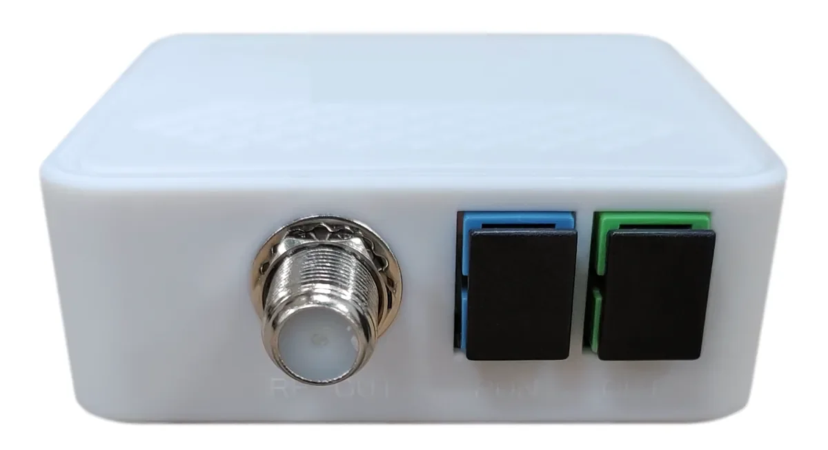
The WDM coupler sits at the headend, after the OLT and the 1550 nm transmitter/EDFA, and before the ODN splitter. It combines the PON wavelengths and the CATV wavelength onto one fibre. At the subscriber end, an ONU with a CATV port separates the 1550 nm signal and delivers RF to the TV.
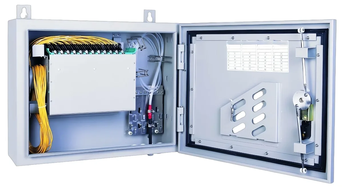
The coupler adds insertion loss to both paths, typically 0.5–1.5 dB. Put that loss in the optical budget before choosing the split ratio. The GPON OLT page covers the PON side, the V2804ACT-A model is an XPON ONT with a 1550 nm CATV receiver and AGC, and the ODF and enclosure page covers the fibre termination. Do not mix SC/UPC and SC/APC without a hybrid patch cord.
What does the CATV receiver need at the wall?
The receiver needs an optical input inside its window, a 75 Ω RF output and an AGC range that covers the installed level. The receiver in this range accepts +2 to −18 dBm at 1550 ± 10 nm, delivers 47–1000 MHz at 75 Ω with AGC, and maintains ≥81 ± 2 dBµV in the AGC window. At −14 dBm input, the MER is ≥32 dB. Those numbers are the pass criteria, not marketing claims.
Measure the optical input and the RF level at commissioning. A receiver that is hot may look fine on one channel and distort on a full lineup; a receiver that is weak may work on analogue and fail on digital. The hotel all-optical page shows the triple-play layout, and the V2804ACT-A page shows the ONT with the CATV port.
What should be measured at commissioning?
Measure the transmitter output, the EDFA input and output, the splitter input and each output, the receiver input and the RF level at the wall. Record the wavelength, the meter, the value and the date. Compare the measured loss with the design and investigate any 2–3 dB discrepancy before accepting the link.
Keep the values in the as-built and re-measure after a splitter change or a fibre repair. A 1550 nm link can pass on day one and drift as connectors age or a splitter port is added. Send the site data or ask on WhatsApp with the transmitter output, the split count and the receiver model; we will return the optical budget and the BOM.
Use this on a real site
Send the endpoint count, the longest run, the mains condition and the load. We will apply this calculation to your project and return the optical/power budget with the bill of materials.