What is Power over Fiber, in practical terms?
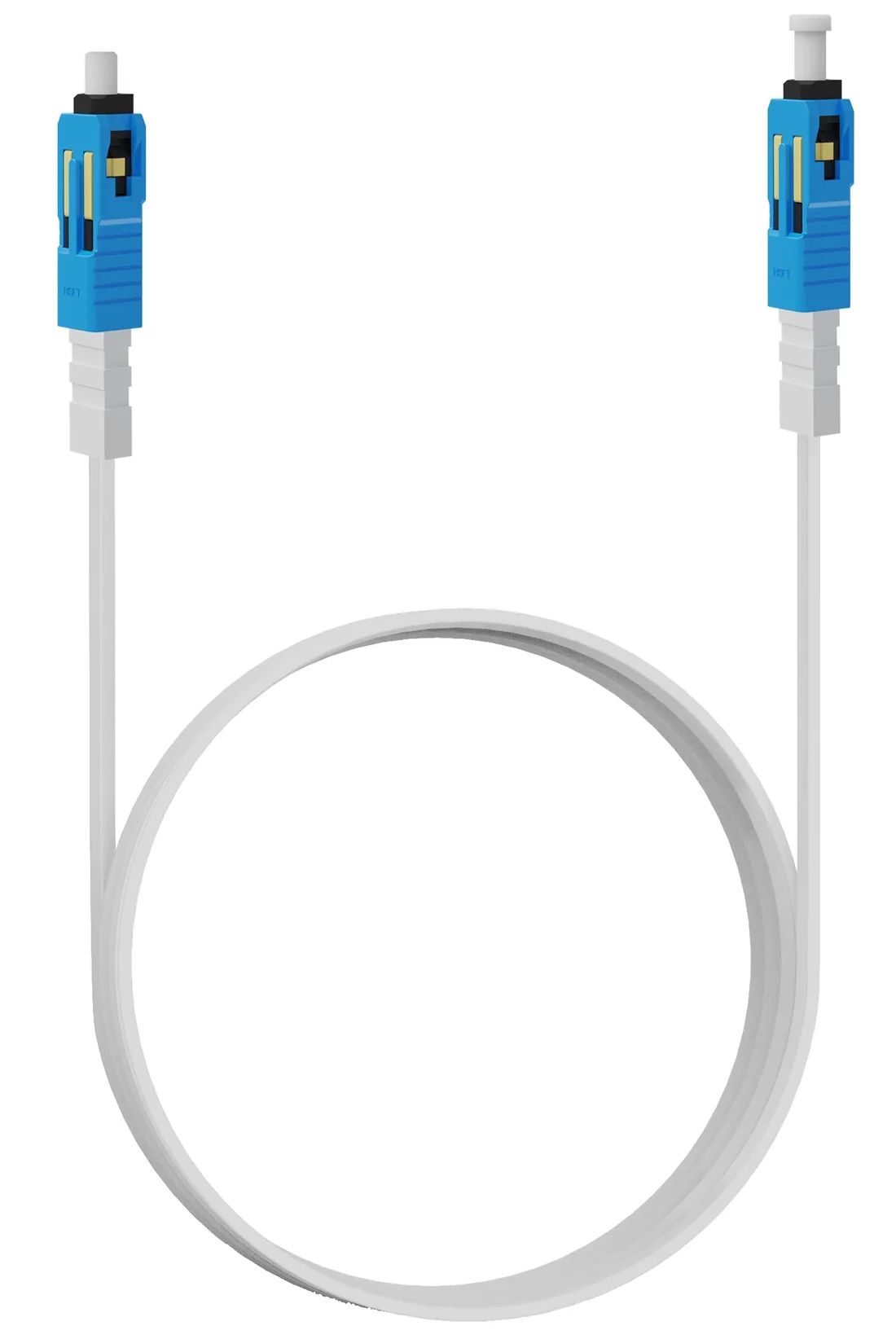
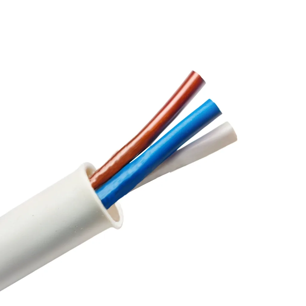
On this site, Power over Fiber means a hybrid cable that carries one optical fibre and a copper pair in the same jacket. The fibre carries the data; the copper carries 48 V DC. One cable replaces a fibre drop plus a local mains spur, so a ceiling AP, a pole camera or an access-control reader can be installed where there is no socket. It is not IEEE PoE over a fibre patch cord, and it does not run on standard fibre cable.
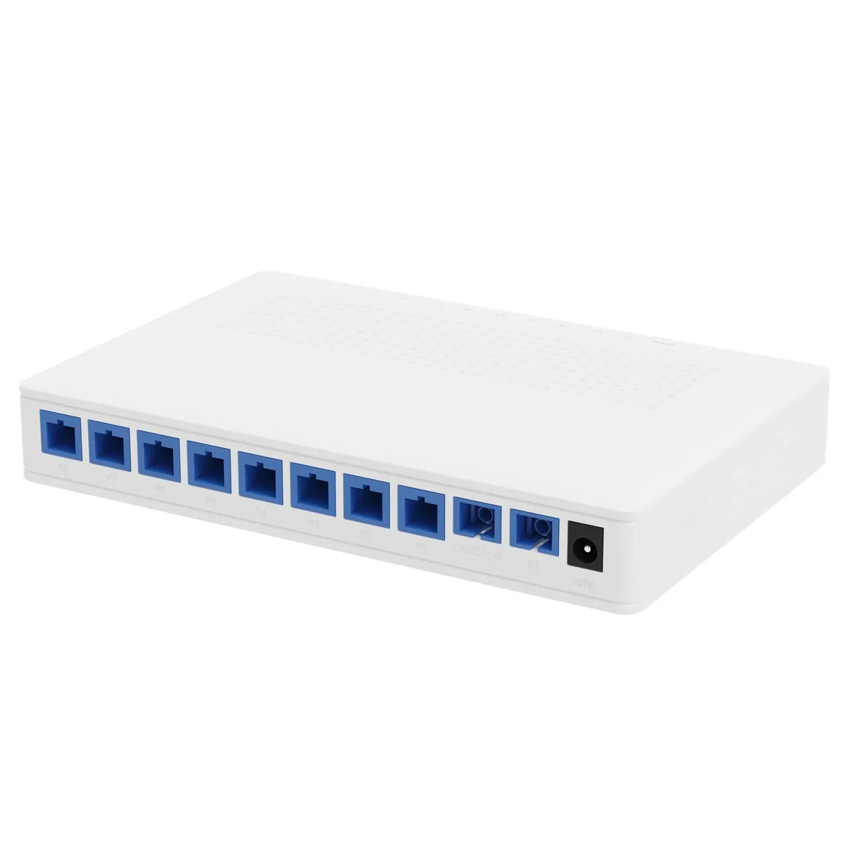
The system has three parts: a PoF gateway or PON headend, a PoF power splitter that distributes both light and DC, and a PoF ONU or PoF AP at the endpoint. The PoF switch and ONU page covers the access set, and the hybrid PoF cable page covers the cable lengths and connectors. The splitter is the part that makes an eight-port floor practical: one input, eight powered outputs and one cascade port.
How much power actually reaches 200 m?
The splitter output is rated at up to 12 W per port with a 120 W supply. That is a port rating, not a promise at every cable length. At 48 V, 12 W is 0.25 A. The copper pair has resistance, so the voltage at the ONU is lower than the voltage at the splitter, and the power available at the load is lower than 12 W. The longer the route and the thinner the copper, the larger the drop.
The calculation is Ohm law plus the cable datasheet. A 200 m route with a 14 Ω loop resistance and a 0.25 A load drops 3.5 V, so the ONU sees about 44.5 V. At constant current that is about 11.1 W at the load, before the ONU conversion loss. A constant-power load draws more current as the voltage falls, so the real drop is slightly larger. Measure the DC voltage at the ONU under load, not the open-circuit voltage. The PoF splitter and V1809P model pages list the 0.25 A rated and 0.5 A maximum output current.
| Route | Example loop resistance | Drop at 0.25 A | Voltage at ONU | Approx. power at load |
|---|---|---|---|---|
| 50 m | 3.5 Ω | 0.9 V | 47.1 V | 11.8 W |
| 100 m | 7 Ω | 1.8 V | 46.2 V | 11.6 W |
| 200 m | 14 Ω | 3.5 V | 44.5 V | 11.1 W |
Example only, assuming a constant 0.25 A load and the stated loop resistance. A constant-power load draws more current as voltage falls; use the cable datasheet and measure under load.
What can run on a 12 W port?
A Wi-Fi 6 ceiling AP at 8–12 W, a fixed camera at 8–12 W and an access-control reader at 8–15 W are the natural loads. A PTZ camera with a heater at 35–60 W is not. A small PoE switch at 15–30 W is not. The 12 W limit is the steady load, not the start-up surge; the ONU and the radio can draw more for a moment, so leave at least 20% headroom.
The power budget is per port and per splitter. Eight outputs at 12 W reach 96 W on a 120 W supply, leaving only 24 W for supply headroom and cable loss. That is why a plan that assumes every port can run at 12 W continuously is already on the edge. If the load is above 12 W, use a local PoE switch or a higher-power design; do not parallel two PoF ports into one device.
| Device | Typical draw | Fits a 12 W port? | Note |
|---|---|---|---|
| Wi-Fi 6 ceiling AP | 8–12 W | Usually | Check the peak radio load |
| Fixed IP camera | 8–12 W | Usually | IR peak may exceed nominal |
| Access-control reader | 8–15 W | Often | Check the lock current |
| PTZ camera with heater | 35–60 W | No | Use local mains or PoE |
| Small PoE switch | 15–30 W | No | Use a local cabinet |
Planning values only. Use the device datasheet and measure the port current at commissioning.
When is PoF better than PoE?
PoF is better when the endpoint is 100–200 m from power, the load is under 12 W and there is no mains at the ceiling or pole. That is exactly the corridor AP, the pole camera or the access reader that would otherwise need a spur, an electrician and a weatherproof socket. It is also useful where a copper Ethernet run would bring a surge path into the ceiling or the pole.
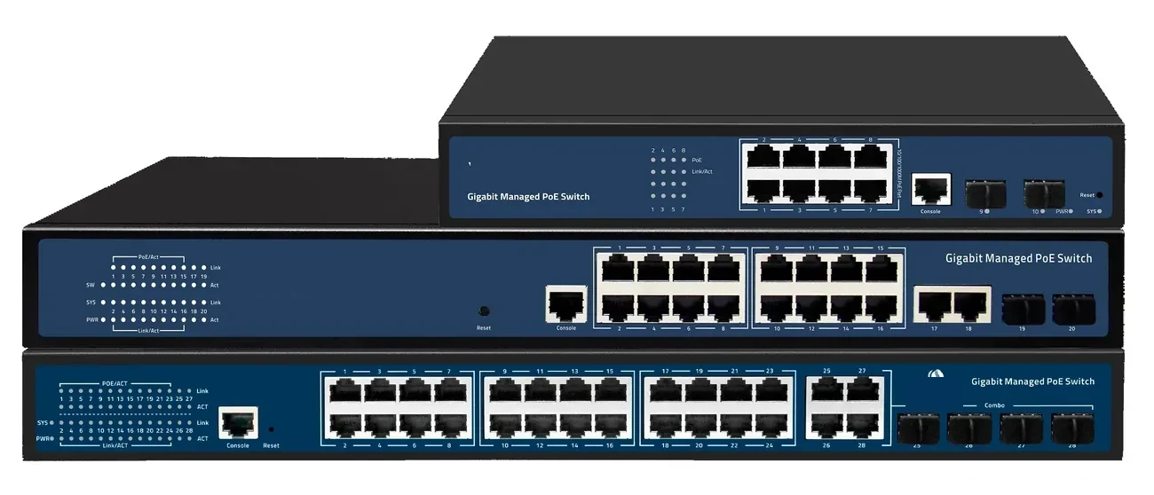
PoE is better inside 100 m where a powered cabinet already exists. It is cheaper, more familiar and supported by every network technician. The PoE switch page covers the copper path; the PoF vs PoE guide compares the two on reach, power, mains and protection. The decision is not ideological: count the endpoints, the distance and the load, then choose the path that removes the most risk.
When is PoF the wrong choice?
PoF is the wrong choice above 12 W per port, beyond 200 m, or where the endpoint needs a standard PoE handshake that the PoF ONU does not provide. A PTZ with a heater, a high-power Wi-Fi 7 AP, a small switch or a device with a 24 V input is not a 12 W PoF load. A cluster of eight cameras at 250 m needs a local cabinet and a PoE switch, not a longer PoF run.
It is also the wrong choice when the site has no plan for the 48 V supply, the SPD and the bonding. The fibre is dielectric, but the hybrid cable still contains a copper pair. A PoF installation without protection at the building entry is a copper installation with a fibre data path. The 24-port PoE switch and industrial PoE switch pages cover the local-cabinet alternative.
What does an 8-output splitter change on site?
An 8-output splitter turns one headend port into eight powered drops. The V1809P is a 1×9 PLC with eight outputs and one cascade port, ≤16.5 dB insertion loss on each output and ≤2.3 dB on the cascade. The cascade port drives a second splitter for 16 APs, but the second stage adds loss to the optical budget and needs its own 120 W supply.
The splitter is also the maintenance point. Label every output with the AP or camera it feeds, record the port map in the as-built, and keep one spare splitter on site for a critical floor. A fault on one output should not take down the other seven; the per-port current limit is there to protect the supply. The PoF splitter page lists the electrical and optical ratings, and the hybrid cable page lists the standard lengths.
What has to be protected and earthed?
The optical path is dielectric, but the 48 V pair is copper. Protect it at the building entry with a suitable SPD, bond the enclosure and the pole, and keep the copper section as short as the route allows. Do not parallel the PoF 48 V rail with a local PoE rail or with a separate adapter; keep the power domains separate and label them. The surge protection page covers the SPD and bonding sequence.
An outdoor PoF AP also needs an IP-rated enclosure, a drip loop and a mounting kit that survives wind. The outdoor wireless coverage page shows the pole layout, and the PoF switch and ONU page covers the ceiling unit. Protection is a system: the SPD, the earth conductor, the enclosure and the cable route all have to be right.
What belongs in the PoF as-built?
Record the splitter location, serial number, input and output port map, the supply model and the measured DC voltage at each ONU under load. Add the optical power at each output, the hybrid cable length and the SPD status. Label both ends of every cable with the port number and the device name.
Update the record when an AP or camera moves. A port that was spare at handover can become a live service after the first expansion; if the label and the record are not updated, the next fault is found on the wrong port. Send the site data or ask on WhatsApp with the endpoint list, the route lengths and the mains condition; we will return the splitter count and the power budget.
- Splitter model, serial number and location.
- Input and output port map, including the cascade port.
- Supply model, 120 W rating and input voltage.
- DC voltage at each ONU under load.
- Optical power at each output and the hybrid cable length.
- SPD status, enclosure IP rating and commissioning date.
Use this on a real site
Send the endpoint count, the longest run, the mains condition and the load. We will apply this calculation to your project and return the optical/power budget with the bill of materials.