What makes an outdoor access point different from an indoor AP?
An outdoor AP has to survive heat, cold, rain, dust, wind and lightning-induced surges. The radio may be similar to an indoor unit, but the enclosure, the mounting, the power path and the surge protection are not. A ceiling AP in a corridor has a conditioned space and a nearby switch; a pole AP has neither. The design starts with the pole, not the Wi-Fi generation.
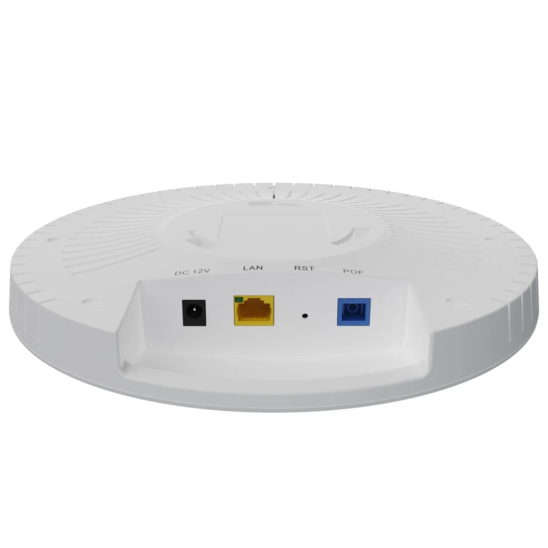
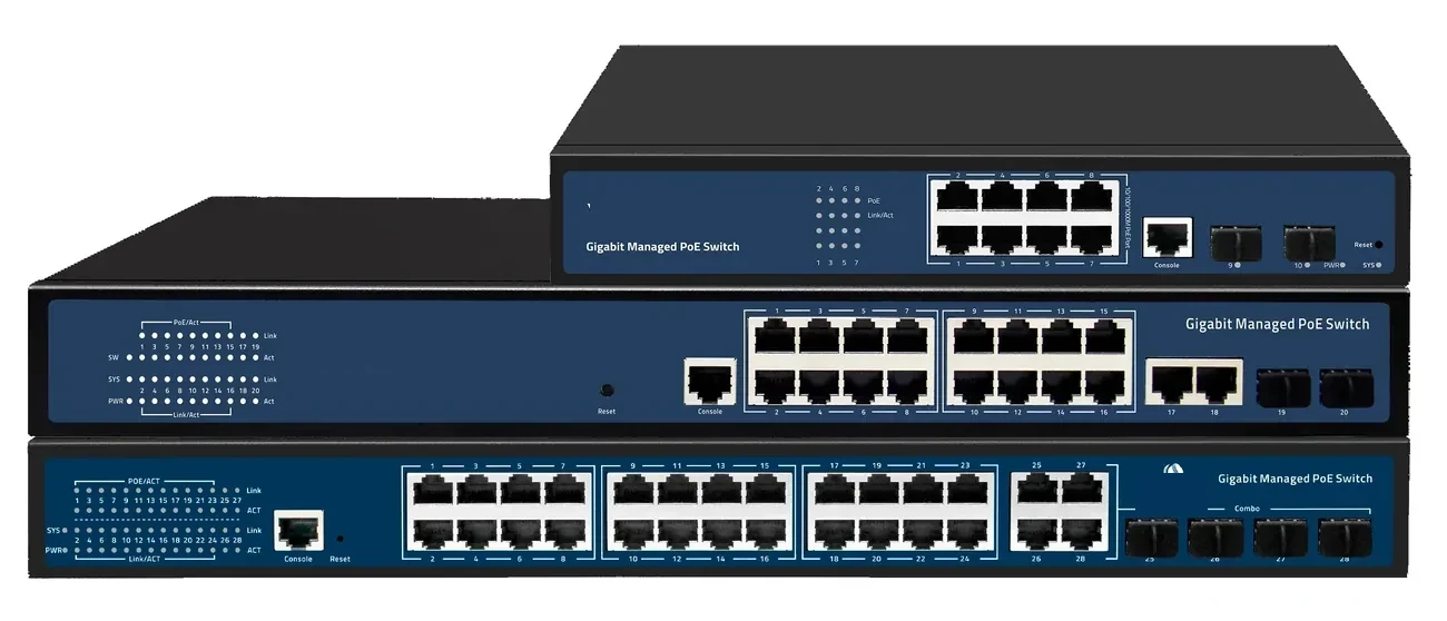
The second difference is the backhaul. An indoor AP usually has a copper run to a switch. An outdoor AP may be 100 m from the cabinet, 200 m from power, or 20 km from the core. The power path and the backhaul have to be chosen together. The Wi-Fi AP and AC page covers ceiling, wall-plate, high-density and PoF models; the industrial PoE switch page covers the hardened cabinet side.
PoE, PoF or local mains: which power path fits the pole?
Copper PoE is the simplest path when a powered cabinet is within 100 m. It delivers 15.4 W or 30 W at the source, but the cable drops voltage and the copper run is a surge path. A PoE extender adds another 100 m per hop, but it needs a power source at the midpoint. Fibre plus a local PoE switch removes the distance limit, but it needs a powered cabinet at the far end. PoF sends data and up to 12 W over one hybrid cable to 200 m, with the power source back at the splitter.
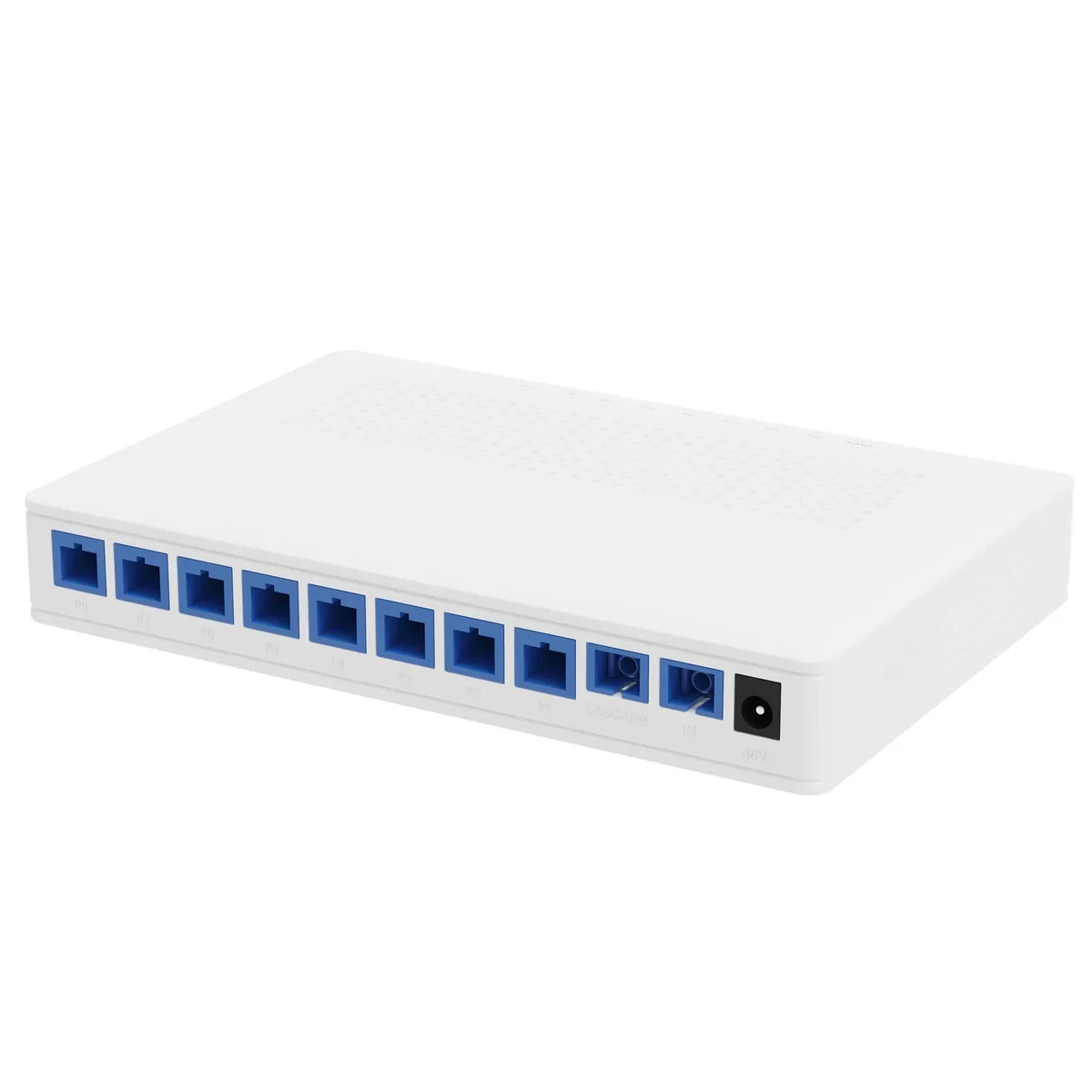
The choice is usually decided by mains and load, not by preference. Inside 100 m with mains, use PoE. At 100–200 m without mains and under 12 W, use PoF. Above 12 W or 200 m, use fibre plus a local switch and a mains feed. Do not design a 40 W AP on a 12 W PoF port. The PoE switch and PoF switch and ONU pages show the two access paths.
| Power path | Reach | Power at endpoint | Mains at pole | Best for | Watch-out |
|---|---|---|---|---|---|
| Copper PoE | 100 m | 15.4 / 30 W at source | No | AP near a powered cabinet | Voltage drop and surge |
| PoE extender | 200–500 m | Reduced per hop | Yes at midpoint | Retrofit with a powered midpoint | Another powered box outdoors |
| PoF | 200 m | Up to 12 W per port | No | No-mains ceiling or pole | 12 W budget and hybrid cable |
| Fibre + local PoE | 20 km PON | Local switch budget | Yes at cabinet | Clusters and buildings | Needs a powered cabinet |
Reach figures are standards or product ratings; the actual limit is the power budget and the optical budget.
How should the AP backhaul be designed?
The backhaul carries the client traffic, the management VLAN and the roaming control traffic. A single AP on a pole can use a copper run if it is within 100 m; a group of APs should use a fibre uplink to a local switch or a PON drop. A PON backhaul is attractive because one OLT port can serve several APs through a splitter, and the fibre is dielectric.
For a PON backhaul, size the splitter and the ONU like any other subscriber. A PoF AP with an XPON input is a subscriber on the PON; a standard AP with a PoE switch needs a fibre-to-Ethernet ONU or a local switch with an SFP uplink. The GPON OLT page covers the headend, the SFP modules page covers the optics, and the PoF splitter page covers the powered distribution.
What do the 100 m, 200 m and 20 km limits mean on site?
The 100 m limit is the copper Ethernet channel, including patch cords. It is a standard, not a suggestion. The 200 m limit is the PoF port rating, and the 20 km limit is the PON reach on standard optics. Each limit answers a different question: copper length, PoF power reach, PON optical budget. A site can be inside the PON reach and outside the PoF power budget, or inside the PoF reach and outside the copper limit.
Measure the route along the tray, not on the site plan. Add the vertical drop, the service loop and both terminations. A 95 m run measured on the ground can become a 103 m channel. The PoE distance guide shows the calculation, the PoF vs PoE guide compares the paths, and the V1600D8 model is an example of a 20 km EPON headend with 1:64 splitting.
What belongs on the pole and in the cabinet?
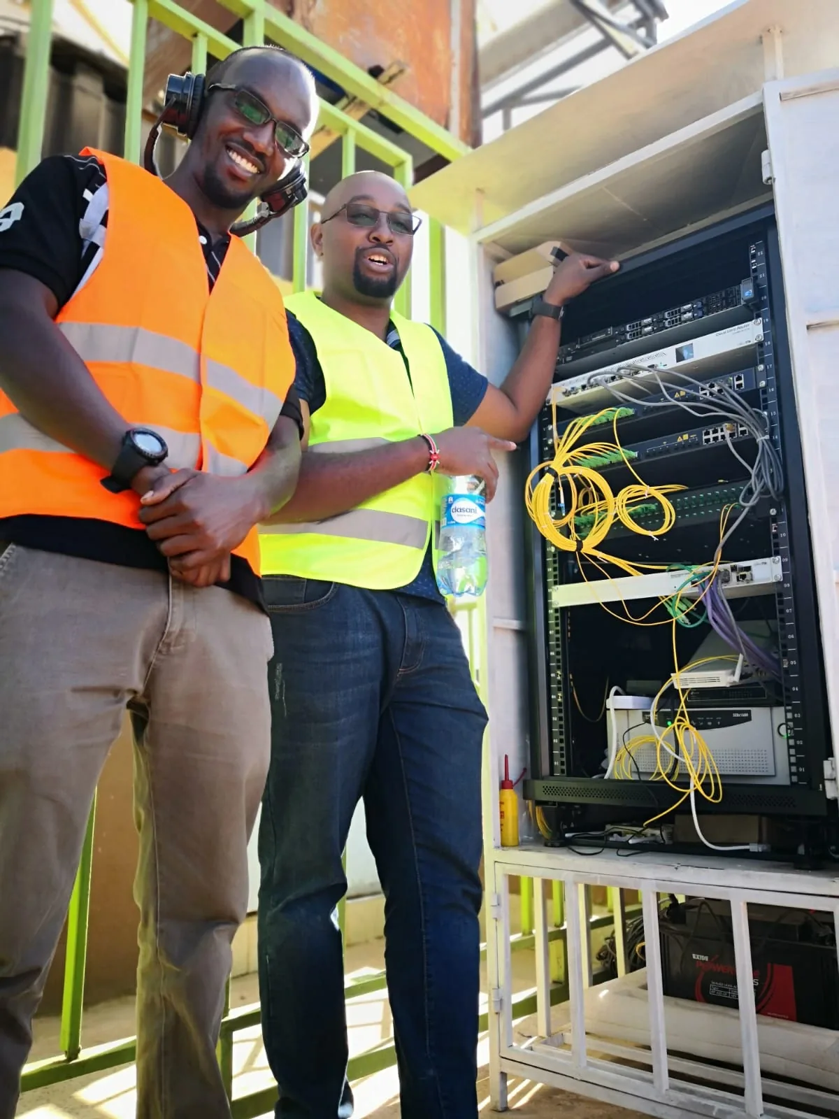
On the pole: the AP, the mounting bracket, the hybrid or copper cable with a drip loop, and the surge protection for the copper pair. In the cabinet: the PoE switch or PoF splitter, the fibre termination, the SPD, the earth bar and the power supply. The AP housing must be rated for the site; the cabinet, not the switch, provides the weather protection.
Bond the pole and the AP housing, keep the earth conductor short and straight, and protect the copper at the building entry. A long earth wire or a loose bond is worse than no protection because it gives a false sense of safety. The surge protection page covers the SPD and bonding sequence, and the outdoor wireless coverage page shows the end-to-end layout.
Which AP class fits a pole, a yard or a campus?
A pole or yard AP needs an outdoor-rated housing, a mounting kit and a power path that survives the weather. A campus corridor AP needs Wi-Fi 6, a 2.5GE uplink and central roaming. A hotel room needs a wall-plate AP, and a hall needs a high-density or Wi-Fi 7 model. The radio class follows the client density; the power path follows the distance and the mains condition.
Do not choose a high-density AP and then power it from a 12 W PoF port. A Wi-Fi 6 AP with a 2.5GE uplink may need 802.3at, and a Wi-Fi 7 AP may need more. Match the PoE class, the uplink and the power source together. The Wi-Fi AP and AC page lists the classes; the V2804AX15-R is a Wi-Fi 6 ONT for a small site, not an outdoor AP.
| Site | AP class | Uplink | Power | Why |
|---|---|---|---|---|
| Hotel corridor | Wi-Fi 6 ceiling AP | 2.5GE | PoE or PoF | No local socket; roaming |
| Office / classroom | Wi-Fi 6 ceiling AP | 2.5GE | PoE | Dense clients |
| Pole / yard | Outdoor AP | GE / fibre | PoE or PoF | Weatherproof and surge |
| Hall / auditorium | High-density / Wi-Fi 7 | 2.5GE / 10GE | PoE | Client density |
| Small site | Wi-Fi 6 ONT | XPON | DC / PoE | One box for access and Wi-Fi |
AP classes and PoE requirements are model-specific. Confirm the uplink, PoE class and enclosure rating on the datasheet.
How many APs and which channels?
A corridor AP every 8–12 rooms is a common starting point for a hotel; an office needs a survey based on wall materials, client density and band. The 2.4 GHz band should be planned for coverage and the 5 GHz band for capacity. Use 20 MHz channels on 2.4 GHz and 40/80 MHz on 5 GHz where the spectrum allows; a wider channel is not always better in a dense area.
The AP count also affects the power budget. Eight PoF APs at 10 W are 80 W, which fits one 120 W splitter with 40 W for cable loss and headroom. Sixteen APs need a second splitter and a second supply. The PoF switch and ONU page covers the 8-output set, and the V1809P page covers the splitter ratings.
What should be in the outdoor AP handover?
Record the AP model, serial number, mounting height, azimuth, channel, transmit power and SSID. Add the power path, the cable length, the measured DC voltage at the AP, the optical power at the ONU and the SPD status. Include a photo of the pole top, the enclosure interior and the earth bond.
Update the record when an AP is moved or a channel is changed. A pole AP that was aligned for a car park may be re-aimed after a building extension; the as-built should show the new azimuth and the new coverage. Send the site data or ask on WhatsApp with the AP count, the pole distances and the mains condition; we will return the power path and the BOM.
- AP model, serial number, mounting height and azimuth.
- Channel, bandwidth, transmit power and SSID.
- Power path, cable length and measured DC voltage.
- Optical power at the ONU and the splitter port.
- SPD status, earth bond and enclosure IP rating.
- Commissioning date, survey file and tester name.
Use this on a real site
Send the endpoint count, the longest run, the mains condition and the load. We will apply this calculation to your project and return the optical/power budget with the bill of materials.