
What does an all-optical hotel network replace?
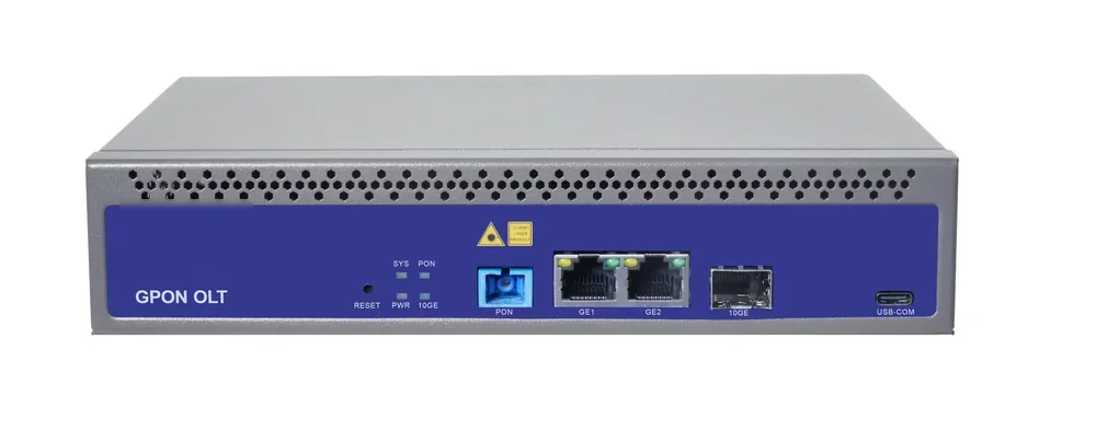
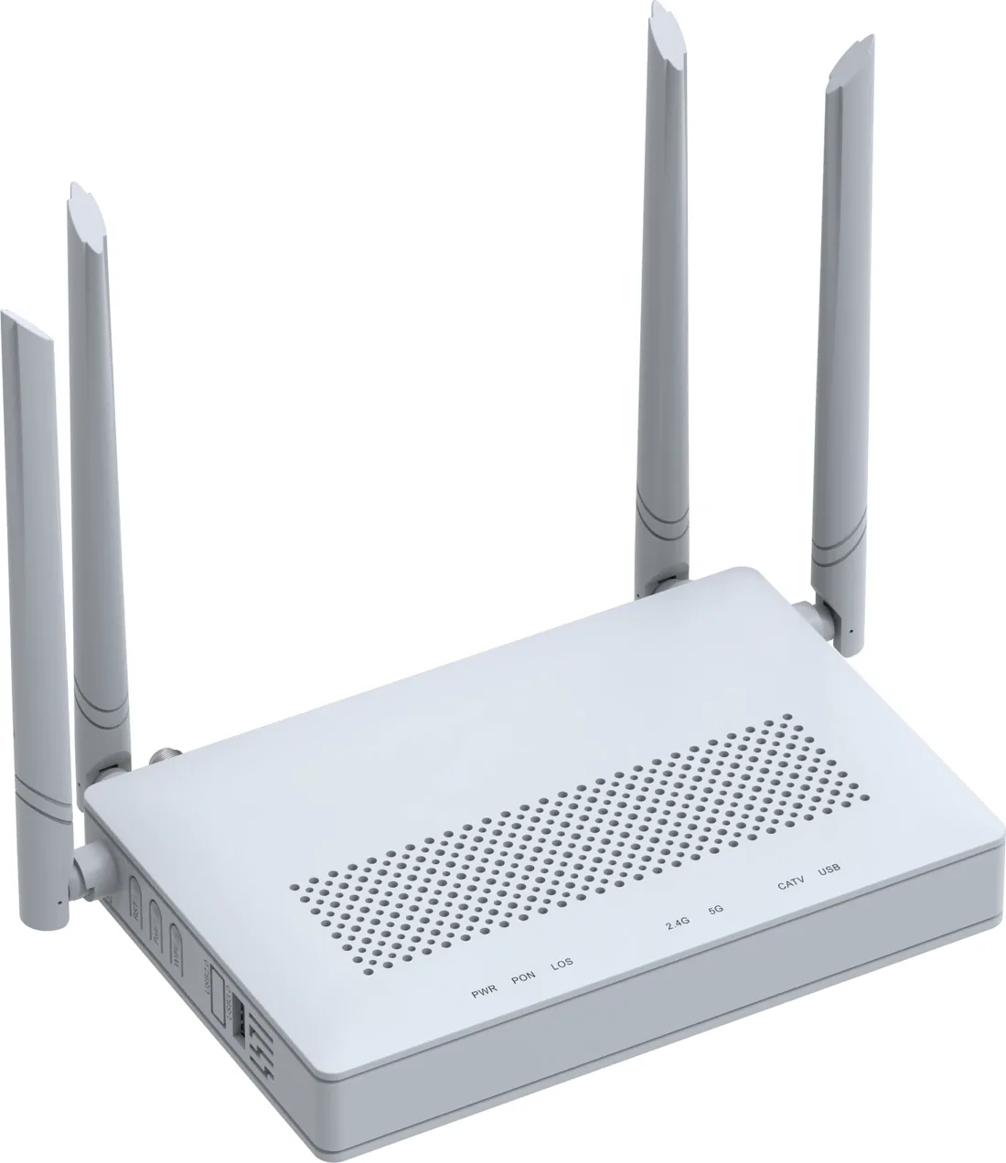
A traditional hotel runs copper from a floor IDF to every room for data, a coax cable for TV and a twisted pair for the phone. An all-optical design replaces the horizontal copper with fibre from an OLT to an ONT in each room; the ONT provides data, Wi-Fi, CATV and optionally POTS. Corridor APs are fed by fibre or by PoF where there is no ceiling mains. The floor IDF switch disappears, but the ONT count and the optical distribution become the new design workload.
The PON choice follows the service mix. GPON gives 2.5 Gbps downstream and 1.25 Gbps upstream, a 1:64 split per port and 20 km reach on Class B+ optics. EPON gives 1.25 Gbps symmetric. XGS-PON gives 10 Gbps symmetric for premium or business floors. Hotel traffic is usually downstream-heavy because of video, so GPON fits; EPON is often chosen where the headend and ONT stock are already EPON; XGS-PON is the upgrade path when multi-gigabit packages are sold. An XGS-PON overlay can share the ODN with GPON through a coexistence element at the headend, provided the splitters and connectors cover the 1270–1577 nm band.
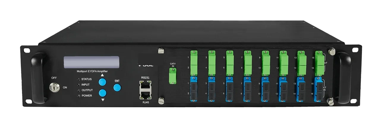
The OLT does not generate CATV. A 1550 nm transmitter and EDFA sit beside it, and a WDM coupler combines the RF overlay with the PON wavelengths. If the hotel buys IPTV from a provider over IP, the CATV overlay may not be needed at all; decide that before the splitter plan, because it changes the ONT model and the headend rack.
| Service | Bearer on the ODN | Headend equipment | Room termination | VLAN note |
|---|---|---|---|---|
| Guest internet | 1490/1310 nm PON | OLT plus splitter | ONT Wi-Fi 6 gateway | One guest VLAN per floor or SSID |
| IPTV / CATV | 1550 nm RF overlay or IP multicast | 1550 nm transmitter, EDFA, WDM coupler | ONT CATV port or IPTV app | RF overlay needs no IPTV VLAN; IP multicast needs IGMP snooping |
| Voice | PON plus voice profile | OLT plus voice gateway | ONT POTS port | Separate voice VLAN and QoS |
| Corridor Wi-Fi | PON or PoF | OLT plus PoF gateway and splitter | Ceiling ONT or AP | Same SSID plan, local VLAN |
| CCTV and access control | PON plus PoE | OLT plus PoE switch or ONU | Camera or controller | Security VLAN, no guest access |
| PMS and back office | PON | OLT plus ONT | ONT bridge or gateway | Staff VLAN with ACL |
One ODN can carry all services if the splitters and connectors are rated for 1310, 1490 and 1550 nm.
How many PON ports does the hotel need?
Count endpoints, not rooms. A guest room normally has one ONT; a suite may have two; corridors need one AP per coverage cell, often 8–12 rooms per AP as a starting point; back office, PMS, security, lifts and plant rooms add ONTs or PoE ONUs. Add 10–15% for spare capacity. Then divide by the split ratio and apply a fill target of 50–70%, not 100%.
For a 120-room hotel, take 120 room ONTs, 18 corridor and public-area APs and 12 back-office or security endpoints, a total of 150. At 1:32, that is 4.7 ports at full fill, so an 8-port OLT gives 150 of 256 capacity, about 59% fill. At 1:64, it is 2.3 ports at full fill; a 4-port OLT gives 59% fill but leaves less room for a second phase. The 8-port OLT with 1:32 is the more comfortable plan; the 4-port OLT with 1:64 is viable only if the optical budget and the ONU count per port are verified.
The 20 km reach is a PON limit, not a hotel requirement. A single building may have 1–3 km of fibre including risers and service loops; a hotel on a campus may have a 5–20 km feeder to the headend. Check the actual route, because the split ratio that passes at 1.5 km may fail at 20 km. The 1:64 splitter costs 20.5 dB before connectors; 1:32 costs 16.5 dB and is the safer choice on a long feeder.
| Area | Endpoints | ONT or device | Split basis | Note |
|---|---|---|---|---|
| Guest rooms | 120 | Wi-Fi 6 ONT, CATV or POTS option | 1 per room | Suites may need a second ONT |
| Corridors and public areas | 18 | Ceiling ONT or AP, PoF or PoE | 1 per coverage cell | Confirm with a site survey |
| Back office and PMS | 8 | Wi-Fi 6 or bridge ONT | 1 per desk group | Staff VLAN |
| Security and CCTV | 4 | PoE ONU or bridge ONT | 1 per cabinet | Separate security VLAN |
| Total | 150 | — | 5 ports at 1:32 full; 3 at 1:64 full | Plan 8 ports at 1:32 or 4 ports at 1:64 |
Fill target 50–70%. Do not plan a port at 100% ONU count and 100% optical loss at the same time.
Which ONT belongs in the room and which in the corridor?
A guest room ONT should be a Wi-Fi 6 gateway with at least four GE ports, a CATV option if the hotel uses an RF overlay, and a POTS option if the room phone stays on the PON. The AX1500 class is enough for a standard room; the AX3000 class suits a suite, a high-density floor or a room used as a small office. One model family across the property keeps the ONT profile, the spare-parts list and the guest-facing Wi-Fi behaviour consistent.
A corridor AP is a different device. It needs a ceiling mount, a PON or PoF input and a radio sized for the corridor, not a desk. The PoF ceiling ONU is a Wi-Fi 6 AX3000 AP with one XPON PoF input and one GE port; it is powered over the hybrid cable and managed by the gateway or OLT. If the corridor has mains and a PoE switch, a standard ceiling ONT or AP is simpler; if the ceiling is 120 m from the cabinet and has no socket, PoF is the reason the AP can be installed there at all.
Do not put a room ONT in a ceiling void without an enclosure and a temperature check. The 4-GE Wi-Fi 6 unit is rated for −10 to +55 °C, which covers many ventilated corridors but not a sealed ceiling box above a kitchen. The ceiling ONU is the right form factor where the network terminates above the guest, not behind the television.
| Location | Recommended unit | Ports | Power | Management |
|---|---|---|---|---|
| Standard guest room | Wi-Fi 6 AX1500 ONT | 4× GE, Wi-Fi 6, CATV or POTS option | DC adapter | OMCI or TR-069 profile |
| Suite or premium room | Wi-Fi 6 AX3000 ONT | 4× GE, USB, Wi-Fi 6 | DC adapter | OMCI or TR-069, mesh where supported |
| Corridor ceiling | PoF ceiling ONU or AP | 1× XPON PoF, 1× GE, Wi-Fi 6 AX3000 | PoF hybrid cable, 12 W port | Gateway software AC or OLT |
| Corridor with mains | Ceiling ONT or PoE AP | 1× PON, 1–2× GE | DC or PoE | OLT or AP controller |
| Back office | Wi-Fi 6 or bridge ONT | 1–4× GE | DC adapter | OLT or ACS |
Confirm the connector polish, CATV and POTS options on the model datasheet before the order.
How do CATV and POTS reach the room on one fibre?
CATV is added at the headend, not by the OLT. A 1550 nm transmitter and an EDFA generate and amplify the RF signal, and a WDM coupler combines 1550 nm with the PON wavelengths on the same ODN. The room ONT needs a 1550 nm CATV receiver port with AGC; the receiver accepts roughly +2 to −18 dBm and delivers 47–1000 MHz at 75 Ω. The optical input must stay inside that window: too high saturates the receiver, too low degrades the RF signal.
The 1550 nm window also has lower fibre loss, about 0.2 dB/km against 0.35 dB/km at 1310 nm, which helps a campus feeder. The same splitter and connectors must work at 1310, 1490 and 1550 nm; standard PLC modules do. For RF, SC/APC connectors are preferred because the angled polish gives at least 60 dB return loss, while SC/UPC gives at least 55 dB. Do not mix polish types without a hybrid patch cord.
POTS is a profile decision as much as a hardware decision. The ONT needs a POTS port and the OLT needs a voice profile and a gateway or softswitch behind it; the room number and the emergency call routing must be provisioned with the voice service. If the hotel keeps an analogue PBX, the ONT POTS port can present a line to the PBX or to the room phone, but the dial plan stays with the PBX. Confirm the model option before the order, because a Wi-Fi 6 ONT without a POTS port cannot be upgraded in the field. If lifeline service is required, the OLT and ONT need UPS backup; the PON itself does not provide line power.
How do you power corridor APs without ceiling mains?
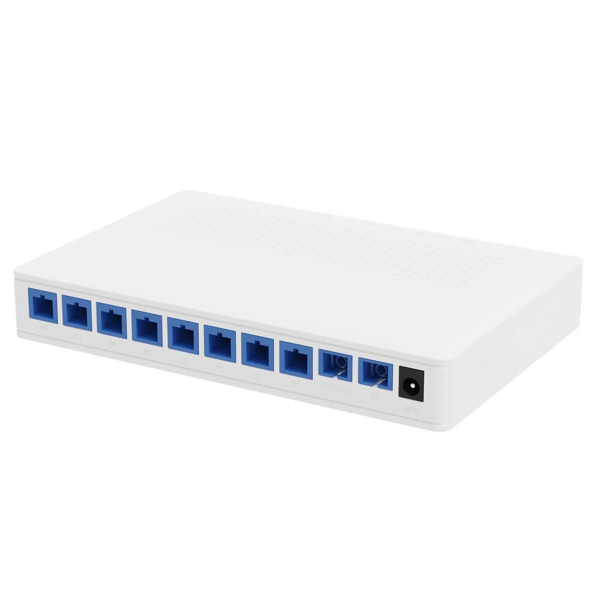
A PoF floor is built around a gateway and one or more splitters. The gateway provides one GPON port, two GE ports and one 10GE SFP+ uplink, with a built-in software access controller. Each PoF splitter takes 48 V DC from a 120 W supply, splits the optical signal 1×9 and delivers up to 12 W per output to 200 m. The ceiling ONU is the AP: Wi-Fi 6 AX3000, one XPON PoF input, one GE port and five internal antennas.
For a floor with 12 corridor APs, use two splitters, for example eight outputs on the first and four on the second. The cascade port links the second splitter to the first and adds 2.3 dB or less to the optical budget; plan a separate 120 W supply for the second splitter, because the cascade does not merge the power budget. Check the PON budget after the cascade, and do not add a third stage without recalculating it. If the AP peak is 15 W, a 12 W port is not enough; use a local PoE switch or a different AP.
PoF is not a way to avoid the optical budget. The splitter output is 16.5 dB, the cascade is 2.3 dB, and the fibre and connectors add their own loss. A PoF floor that sits 1 km from the OLT is easy; a PoF floor at the end of a 20 km campus feeder needs the same calculation as any other PON extension. The power side and the optical side share the cable but not the budget.
- Keep AP load at or below 10 W for 20% headroom on a 12 W port.
- Use one 120 W supply per eight-port splitter.
- Label each PoF output by AP name and floor.
- Check the PON budget after every cascade.
What VLAN plan keeps guest, staff and building traffic apart?
A hotel VLAN plan has to separate guest internet, staff and PMS, voice, IPTV, CCTV, access control and network management. Guest devices should not reach the PMS or the camera network, and a guest SSID should not be able to broadcast into the corridor AP management VLAN. The OLT can push a service profile to each ONT; the profile should include the VLAN, the SSID, the bandwidth limit and any multicast setting.
Two details cause most hotel faults. First, IPTV multicast without IGMP snooping floods every access port and can saturate a floor; enable snooping and make the recorder or router the querier. Second, guest VLANs that are bridged between floors let a guest device discover another guest device; use client isolation and a per-floor or per-SSID VLAN. Neither feature costs a truck roll if it is in the profile from day one.
QinQ is useful when the hotel sells conference or long-stay space to a tenant with its own VLAN range. It keeps the tenant VLANs transparent across the building network and lets the hotel apply a single outer VLAN. It is not needed for a standard guest network, and enabling it without a written plan makes fault finding harder.
| VLAN (example) | Service | Endpoint | QoS or isolation |
|---|---|---|---|
| 10 | Guest internet | Room ONT guest SSID and GE ports | Rate limit per room, client isolation |
| 20 | Staff and PMS | Back-office ONT, front desk | ACL to PMS servers only |
| 30 | Voice | ONT POTS port | Priority queue, dedicated bandwidth |
| 40 | IPTV multicast | Room ONT or IPTV app | IGMP snooping, multicast VLAN |
| 50 | CCTV and security | PoE ONU, cameras, recorder | No guest route, recorder on a trunk port |
| 60 | Access control | Controller and readers | Restricted ACL |
| 70 | Management | OLT, ONTs, APs, switches | Management ACL, no data-plane access |
VLAN IDs are examples. Keep the same plan across OLT, ONT profiles and switches.
How do you prove the 20 km and 1:64 budget on a hotel ODN?
Start with the actual OLT transmit power and ONT sensitivity. A Class B+ link is often budgeted at 28–30 dB depending on the optic; the worked example here uses +3 dBm transmit and −27 dBm sensitivity, a 30 dB budget. Subtract the splitter, fibre, connectors, splices and a 3 dB ageing margin. The result must be positive for the worst-case port, not the average port. The full derivation, including the CATV overlay case, is in the optical link budget guide.
The table explains the usual hotel recommendation. Inside one building, 1:64 is comfortable because the fibre is short. On a 20 km campus feeder, 1:64 fails even before the worst-case port; 1:32 passes, but only with a small residual after the 3 dB ageing reserve. If the route has more connectors, more splices or a higher-loss splitter, drop to 1:16 or move the splitter closer to the building.
The worst-case port also depends on splitter uniformity. A 1:64 splitter with 2.5 dB uniformity can put the weakest port 2.5 dB below the best. If the design margin after ageing is only 0.7 dB, that port is already outside the plan. Ask for per-port test data, and put the weakest port on the shortest drop or use a lower ratio. The field method is set out in the FTTH splitter planning notes.
| Scenario | Split | Splitter loss | Fibre loss | Connectors | Splices | Total | Margin, then after 3 dB |
|---|---|---|---|---|---|---|---|
| In-building, 1.5 km | 1:64 | 20.5 dB | 0.5 dB | 2.4 dB (6 pairs) | 0.4 dB (4) | 23.8 dB | 6.2 dB, then 3.2 dB |
| Campus feeder, 20 km | 1:32 | 16.5 dB | 7.0 dB | 2.4 dB (6 pairs) | 0.4 dB (4) | 26.3 dB | 3.7 dB, then 0.7 dB |
| Campus feeder, 20 km | 1:64 | 20.5 dB | 7.0 dB | 2.4 dB (6 pairs) | 0.4 dB (4) | 30.3 dB | −0.3 dB, fails |
Use 0.35 dB/km at 1310 nm, 0.3–0.5 dB per connector pair and 0.1 dB per splice. Verify with per-port test data.
What should the hotel as-built and room handover include?
For each room, record the room number, ONT serial and MAC, PON port, splitter port, measured optical receive power, VLAN and SSID profile, CATV level if present, POTS number if present, firmware version and test date. For each floor, record the splitter ID and ratio, the per-port insertion loss, the PoF port map and the AP channel and power. At the headend, record the OLT port map, uplink, VLAN plan, ONT profiles, power feed and spare ports.
Keep 2–3% spare ONTs, one spare PoF splitter and one spare ceiling AP for a property of this size. Label the splitter outputs by room range or AP name, not by port number alone. The as-built should be updated when a room is converted, an AP is added or a splitter port is moved; an outdated map is worse than no map because it sends the technician to the wrong port.
- Room-to-ONT map with serial, PON port, splitter port and optical power.
- Floor splitter record with per-port loss and spare outputs.
- PoF port map by AP name, with the 120 W supply assigned to each splitter.
- VLAN, SSID and bandwidth profile for every ONT.
- Headend port map, uplink, power feed and management address.
Use this on a real site
Send the endpoint count, the longest run, the mains condition and the load. We will apply this calculation to your project and return the optical/power budget with the bill of materials.