
What belongs in the pole load list before anyone chooses a cable?
Pole power design starts with a table, not a product. For every pole, record the camera type, nominal and peak draw, mounting height, route length from the nearest powered cabinet, whether mains is present, and any other load on the same pole such as an access point, illuminator or sensor. A fixed dome at 8 W and a PTZ with a heater at 35 W look similar on a one-line drawing but need different power paths.
Route length is not the distance on the site plan. Measure the vertical drop, the cable tray, the service loop at each end and both terminations. The PoE channel is 100 m including patch cords, so a 95 m run measured along the ground can become a 103 m channel once the cabinet and camera ends are counted. A PoF port is rated to 200 m, but the same route discipline applies.
| Survey field | Why it decides the path | Example entry |
|---|---|---|
| Camera type and mount | Fixed, PTZ, LPR or multi-sensor; determines peak load and protocol | Fixed bullet, 4 m pole |
| Nominal and peak watts | Peak with IR, heater or pan and tilt sets the port class | 8 W nominal, 11 W peak |
| Route length | Compared with the 100 m PoE channel and the 200 m PoF port | 118 m along tray, plus 3 m drop |
| Mains at the pole | Decides whether a local PoE switch or a PoF drop is possible | No socket; nearest board 120 m away |
| Other loads on the pole | Shares the port, the splitter budget or the switch budget | One AP at 10 W |
| Surge exposure | Sets the SPD class, earthing and cable route | Open lot, high lightning exposure |
| Maintenance access | Decides where the splitter or switch can be serviced | Pole reached by ladder only |
The load list is the design record. Update it when a camera or illuminator is added.
How much power does a pole camera really draw?
Use measured or nameplate peak values, not an average. A fixed dome typically draws 6–12 W; a bullet with IR can reach 12–14 W at night; a PTZ with pan, tilt and a heater can reach 25–60 W; a license-plate camera with its own illuminator can push a nominally small camera above 12 W. Start-up inrush is a separate question from steady draw, but the port class and the supply budget must cover the steady peak first.
The PoF limit is 12 W per port, not 12 W average. At 48 V DC, 12 W is 0.25 A, which is the rated current of one splitter output; 0.5 A is a short-term maximum, not a continuous load. Eight outputs at 12 W reach 96 W on a 120 W supply, leaving only 24 W for supply headroom and cable loss. A plan that assumes every port can run at 12 W continuously is already on the edge.
Diversity matters at the supply, not at the port. Eight cameras rarely peak at the same instant, but the splitter supply and the PoE budget are sized on the connected load, because a cold night can bring heaters and IR on together. Use the sum of peaks for the supply calculation and note where diversity is claimed; a 120 W supply with 96 W of connected PoF load has 24 W of headroom before cable loss, which is the honest number.
| Camera class | Nominal draw | Peak to record | Candidate path | Watch-out |
|---|---|---|---|---|
| Fixed dome | 6–10 W | 8–12 W with IR | PoE within 100 m; PoF if no mains and within 200 m | IR on and off changes port load |
| Fixed bullet | 6–12 W | 8–14 W with IR | PoE or PoF | Long runs add voltage drop |
| PTZ | 20–30 W | 35–60 W with heater | 802.3at PoE or local switch | PoF only if the peak stays under 12 W |
| LPR / ANPR | 10–15 W | 15–30 W with illuminator | Local PoE switch or mains | Illuminator is often omitted from the load list |
| Pole AP | 10–15 W | 15–20 W | PoE or PoF | Wi-Fi 6 peak can exceed the nominal class |
Ranges are planning values. Use the device datasheet and a clamp meter at commissioning.
When is a PoE switch still the right answer at a pole?
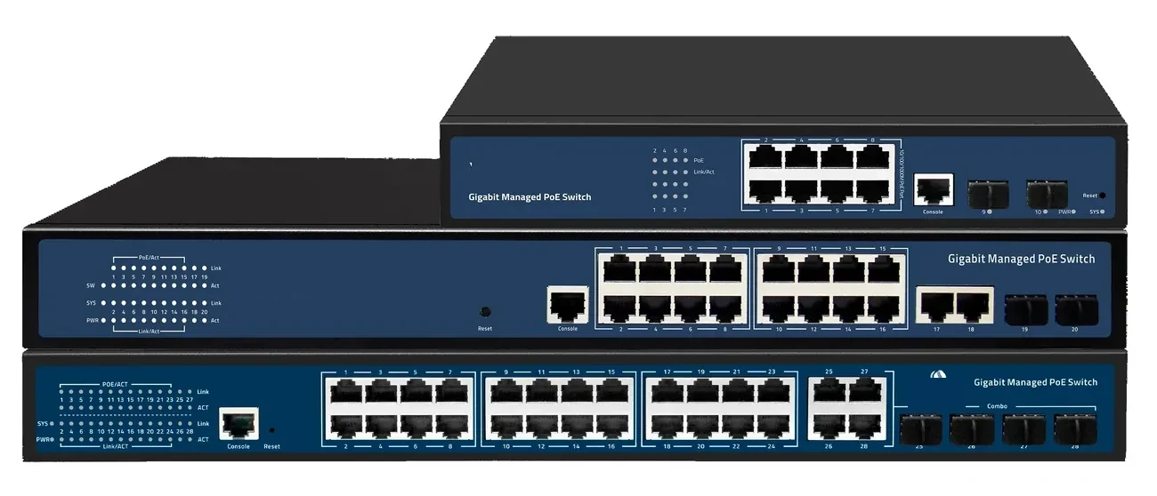
If a powered cabinet is within the 100 m channel and the camera fits an 802.3af or 802.3at class, copper PoE is the cheapest and most familiar path. Keep the switch indoors or in a bonded cabinet, not in a sealed box on the pole. Check the total budget, not only the per-port label: a 24-port switch with a 370 W budget cannot run 24 heated PTZs at 30 W each.
Voltage drop decides many marginal designs. At 30 W and 48 V the current is about 0.63 A; a 100 m loop of 24 AWG copper has roughly 20 Ω, so the round trip drops about 12.6 V. The camera sees about 35 V, not 48 V. Check the minimum input voltage on the camera datasheet, not only its wattage. The calculation is set out in the PoE distance guide; the field point here is that a camera can boot on the bench and reset at night on the pole.
Category does not extend the limit. Cat5e, Cat6, Cat6a and Cat7 all carry Ethernet over a 100 m channel; the category changes bandwidth, loss and heat. A longer copper run than 100 m is not a PoE design, whatever the cable label says.
What changes when the pole is 100 m to 200 m away?
Three paths are available, and each moves the power problem rather than removing it. A PoE extender repeats the data and power for another 100 m per hop, but it needs a power source at the midpoint. A fibre link with a local PoE switch removes the distance limit but needs a powered cabinet at the far end. PoF sends data and up to 12 W over one hybrid cable to 200 m, with the power source back at the splitter.
A cluster changes the arithmetic. Eight cameras at 180 m with no mains can be fed by eight PoF drops from one splitter, but the same eight cameras at 250 m need a local cabinet and a PoE switch. For a single 8 W camera at 160 m, PoF is usually the cleanest path; for a 40 W PTZ at the same distance, neither PoF nor a single extender is suitable. The comparison guide covers the decision in more detail.
Maintenance is part of the path decision. An extender adds a powered box at the midpoint, a local cabinet adds a switch and a power feed, and a PoF splitter adds one powered headend point for eight poles. Each option has a different spare-parts list and a different failure mode. A site with no local electrician should not depend on a midpoint supply that nobody can reset; a site with a maintained cabinet can use either copper or fibre.
On hardware alone, a PoE extender can look cheaper than a PoF splitter and PoF ONU. The midpoint power, the weatherproof enclosure and the electrician belong in the installed cost, and they usually decide the comparison. The cost article separates those lines.
| Situation | First choice | Alternative | Avoid |
|---|---|---|---|
| Under 100 m, mains at pole, 30 W or less | PoE switch | Local PoE switch in the cabinet | Long copper run without a voltage-drop check |
| Under 100 m, no mains, 12 W or less | PoF drop | Fibre plus local PoE with a new mains feed | PoE from a distant cabinet |
| 100–200 m, no mains, 12 W or less | PoF drop | Fibre plus local switch if a cluster justifies it | PoE extender without a midpoint supply |
| 100–200 m, no mains, above 12 W | Fibre plus local switch and mains | Local mains feed plus PoE | PoF beyond 12 W |
| Over 200 m, any load | Fibre plus local switch | Point-to-point fibre and a local cabinet | PoF or a copper home run |
The load is the peak draw, not the nominal label.
How do you keep a PoF pole run inside 12 W and 200 m?
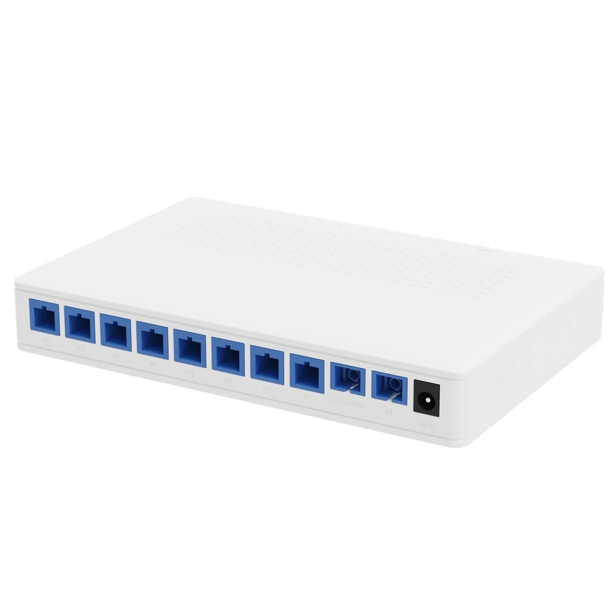
A PoF splitter has eight powered outputs plus one cascade port, takes 48 V DC from a 120 W supply and delivers up to 12 W per output. The splitter is also a 1×9 PLC with 16.5 dB or less insertion loss on each output and 2.3 dB or less on the cascade port. That 16.5 dB is the same order as a 1:32 PON splitter, so the optical budget must be checked before the cable is ordered, not after the ONU fails to register.
Power and voltage drop are the second budget. A 12 W load at 48 V draws 0.25 A. If the cable and connectors drop 6 V at that current, the ONU sees 42 V and the delivered power at the load is about 10.5 W, not 12 W. Use the loop resistance from the hybrid cable datasheet, account for both conductors, and leave at least 20% headroom. A 200 m run has roughly four times the drop of a 50 m run at the same current, so a design that works at 50 m may not work at the far pole.
One splitter per eight outputs is the practical rule. The cascade port extends the optical bus to a second splitter and adds 2.3 dB; it does not merge the power budget. Plan a separate 120 W supply for the second splitter and check the PON budget for the extra loss. Standard hybrid cable lengths are 3, 20 and 50 m, with custom lengths available; measure the route along the tray and add a 1 m service loop at each end.
- Record the measured DC voltage at the ONU under load, not the open-circuit voltage.
- Label each output with the pole ID and camera name.
- Keep 20% headroom on both the splitter supply and the optical budget.
- Use an IP-rated enclosure and a drip loop outdoors.
Where do surge protection and earthing enter the checklist?
A copper Ethernet run to a pole is a lightning path. A nearby strike raises the earth potential at the pole and at the building; the cable shield, camera housing and switch port sit at different potentials, and the current finds the weakest insulation. A Type 2 SPD at the building or cabinet entry, a short and straight earth conductor, a bonded camera housing and a local earth electrode at the pole are a system, not optional accessories. An SPD with a long earth wire is a false sense of protection.
PoF removes the metallic data path, which is a real improvement, but the hybrid cable still contains a 48 V copper pair. Protect that pair at the building entry, bond the pole and the camera housing, and keep the copper section as short as the route allows. Do not parallel the PoF 48 V rail with a PoE rail or with a local supply; keep the two power domains separate and label them. The surge guide covers the protection sequence.
Earthing is also a maintenance item. Check the SPD status indicator after a storm, inspect the earth connection at the pole, and replace a failed SPD rather than waiting for the next event. Record the earth resistance if local code requires it; do not assume the pole is earthed because it is metal.
What should be in the pole power handover pack?
The handover pack is the difference between a maintainable site and a puzzle. For each pole, record the device, peak load, power path, switch port or splitter output, cable length, measured optical power at the ONU, DC voltage at the ONU under load, SPD status and the test date. Add a photo of the pole top and the enclosure interior, and label both ends of every cable with the pole ID.
Keep one spare PoF splitter, one spare PoE switch and a spare hybrid cable on site for critical groups. Update the load list when a camera, illuminator or AP is added; a port that was within 12 W at handover can exceed the limit after a device upgrade. The as-built is a living document, not a filing cabinet item.
| Record | Target or reference | Why it matters |
|---|---|---|
| PoE channel length | 100 m or less including patch cords | The standard limit; longer runs may boot but fail under load |
| PoF route length | 200 m or less per port | The system rating; voltage drop rises with length |
| PoF port load | 10 W or less planned, 12 W port maximum | Protects the supply and the ONU input |
| ONU input voltage | Above the ONU minimum under load | Open-circuit voltage hides cable loss |
| Optical power at ONU | Within the design value and at least 3 dB margin | Confirms the splitter and connector loss |
| SPD status | Indicator normal, earth bonded | A failed SPD looks like a working one |
| Labels | Pole ID on cable and splitter output | Fault finding starts with the port number |
Attach the measured values, not only a pass mark.
In what order should the checklist be used?
Survey the poles, build the load list, then choose the path. Calculate the optical and power budgets for the chosen path, confirm the protection and earthing, install, measure, and hand over the records. Do not start with a product and work backwards; the pole, the distance and the mains condition decide the architecture.
A checklist that ends at the purchase order is incomplete. The last step is the record that lets the next technician test the same port against the same number.
- Survey: route, mains, load, shared devices, exposure.
- Load list: nominal and peak watts for every device.
- Path: PoE, extender, fibre plus switch, or PoF.
- Budget: optical loss, voltage drop, supply headroom.
- Protection: SPD, bonding, earth, enclosure.
- Handover: measurements, labels, spares, updated load list.
Use this on a real site
Send the endpoint count, the longest run, the mains condition and the load. We will apply this calculation to your project and return the optical/power budget with the bill of materials.